Theory of operation – PASCO OS-9257A PRECISION INTERFEROMETER User Manual
Page 8
Precision Interferometer
012-07137A
4
Interference Theory
A beam of light can be modeled as a wave of oscillating
electric and magnetic fields. When two or more beams of
light meet in space, these fields add according to the
principle of superposition. That is, at each point in space,
the electric and magnetic fields are determined as the
vector sum of the fields of the separate beams.
If each beam of light originates from a separate source,
there is generally no fixed relationship between the electro-
magnetic oscillations in the beams. At any instant in time
there will be points in space where the fields add to
produce a maximum field strength. However, the oscilla-
tions of visible light are far faster than the human eye can
apprehend. Since there is no fixed relationship between
the oscillations, a point at which there is a maximum at one
instant may have a minimum at the next instant. The
human eye averages these results and perceives a uniform
intensity of light.
If the beams of light originate from the same source, there
is generally some degree of correlation between the
frequency and phase of the oscillations. At one point in
space the light from the beams may be continually in
phase. In this case, the combined field will always be a
maximum and a bright spot will be seen. At another point
the light from the beams may be continually out of phase
and a minima, or dark spot, will be seen.
Thomas Young was one of the first to design a method for
producing such an interference pattern. He allowed a
single, narrow beam of light to fall on two narrow, closely
spaced slits. Opposite the slits he placed a viewing screen.
Where the light from the two slits struck the screen, a
regular pattern of dark and bright bands appeared. When
first performed, Youngs experiment offered important
evidence for the wave nature of light.
Youngs slits can be used as a simple interferometer. If
the spacing between the slits is known, the spacing of the
maxima and minima can be used to determine the wave-
length of the light. Conversely, if the wavelength of the
light is known, the spacing of the slits could be determined
from the interference patterns.
Theory of Operation
The Michelson Interferometer
In 1881, 78 years after Young introduced his two-slit
experiment, A.A. Michelson designed and built an interfer-
ometer using a similar principle. Originally Michelson
designed his interferometer as a means to test for the
existence of the ether, a hypothesized medium in which
light propagated. Due in part to his efforts, the ether is no
longer considered a viable hypothesis. But beyond this,
Michelsons interferometer has become a widely used
instrument for measuring the wavelength of light, for using
the wavelength of a known light source to measure
extremely small distances, and for investigating optical
media.
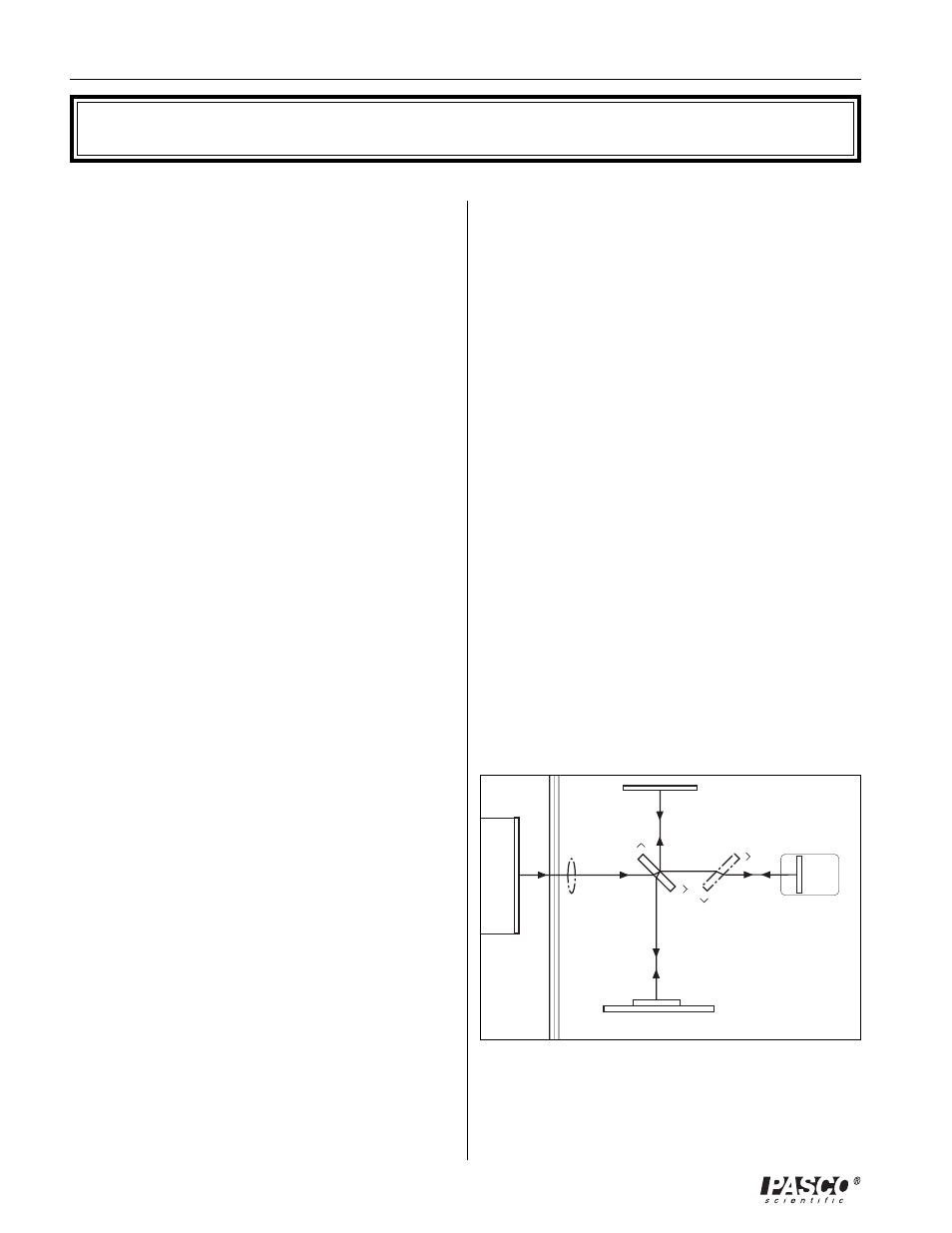
Figure 1 shows a diagram of a Michelson interferometer.
The beam of light from the laser strikes the beam-splitter,
which reflects 50% of the incident light and transmits the
other 50%. The incident beam is therefore split into two
beams; one beam is transmitted toward the movable mirror
(M
1
), the other is reflected toward the fixed mirror (M
2
).
Both mirrors reflect the light directly back toward the
beam-splitter. Half the light from M
1
is reflected from the
beam-splitter to the viewing screen and half the light from
M
2
is transmitted through the beam-splitter to the viewing
screen.
Adjustable Mirror
(M
2
)
Movable Mirror
(M
1
)
Compensator
Plate
Viewing Screen
Beam
Splitter
Lens
Laser
Figure 1. Michelson Interferometer