Experiment 2: the index of refraction of air, Introduction, Procedure 1 – PASCO OS-9257A PRECISION INTERFEROMETER User Manual
Page 17: Where l
13
012-07137A
Precision Interferometer
Experiment 2: The Index of Refraction of Air
EQUIPMENT NEEDED:
Basic Interferometer (OS-9255A)
Laser (OS-9171)
Laser Alignment Bench (OS-9172)
Interferometer Accessories (OS-9256A)
Rotational pointer, Vacuum cell, Vacuum pump
Introduction
In the Michelson interferometer, the characteristics of the
fringe pattern depend on the phase relationships between
the two interfering beams. There are two ways to change
the phase relationships. One way is to change the distance
traveled by one or both beams (by moving the movable
mirror, for example). Another way is to change the
medium through which one or both of the beams pass.
Either method will influence the interference pattern. In
this experiment you will use the second method to
measure the index of refraction for air.
For light of a specific frequency, the wavelength l varies
according to the formula:
l = l
o
/n;
where l
o
is the wavelength of the light in a vacuum, and
n is the index of refraction for the material in which the
light is propagating. For reasonably low pressures, the
index of refraction for a gas varies linearly with the gas
pressure. Of course for a vacuum, where the pressure is
zero, the index of refraction is exactly 1. A graph of
index of refraction versus pressure for a gas is shown in
Figure 2.1. By experimentally determining the slope, the
index of refraction of air can be determined at various
pressures.
Procedure
1.
Align the laser and interferometer in the Michelson mode. See Setup and Operation.
2.
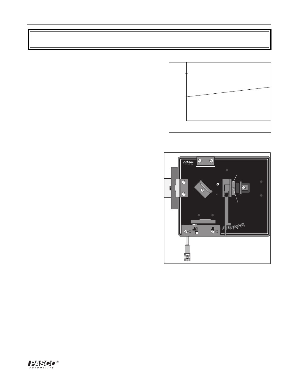
Place the rotational pointer between the movable mirror and the beam-splitter (see Figure 2.2).
Attach the vacuum cell to its magnetic backing and push the air hose of the vacuum pump over the
air outlet hole of the cell. Adjust the alignment of the fixed mirror as needed so the center of the
interference pattern is clearly visible on the viewing screen. (The fringe pattern will be somewhat
distorted by irregularities in the glass end-plates of the vacuum cell. This is not a problem.)
3.
For accurate measurements, the end-plates of the vacuum cell must be perpendicular to the laser
beam. Rotate the cell and observe the fringes. Based on your observations, how can you be sure
that the vacuum cell is properly aligned?
2
1
0
0
Index of Refraction (n)
Gas Pressure (cm Hg)
Figure 2.1. Index of Refraction versus Gas
Pressure
OS-9255A
PRECISION
INTERFEROMETER
-5
0
5
10
15
25
30
ADJUSTABLE MIRROR
MICHELSON, TWYMAN-GREEN
BEAM SPLITTER
MICHELSON
COMPENSA
TO
R
MICHELSON
18 mm FL
LENS
VIEWING SCREEN
MICHELSON, TWYMAN-GREEN
1 div = 1 MICRON
Vacuum Cell
Air Outlet
Figure 2.2. Equipment Setup