Experiment 3: the index of refraction of glass, Introduction, Procedure 1 – PASCO OS-9257A PRECISION INTERFEROMETER User Manual
Page 19: Equipment needed, Figure 3.1. equipment setup
15
012-07137A
Precision Interferometer
OS-9255A
PRECISION
INTERFEROMETER
-5
0
5
10
15
25
30
ADJUSTABLE MIRROR
MICHELSON, TWYMAN-GREEN
B
E
A
M
S
P
LI
TT
E
R
M
IC
H
E
LS
O
N
C
O
M
P
E
N
S
AT
O
R
M
IC
H
E
LS
O
N
18 mm FL
LENS
VIEWING SCREEN
MICHELSON, TWYMAN-GREEN
1 div = 1 MICRON
Experiment 3: The Index of Refraction of Glass
EQUIPMENT NEEDED:
Basic Interferometer (OS-9255A)
Laser (OS-9171)
Laser Alignment Bench (OS-9172)
Interferometer Accessories
Rotating Table, Glass Plate
Introduction
In Experiment 2, the index of refraction of air was
measured by slowly varying the density of air along a
fixed length of one beam path in the Michelson
Interferometer. That method obviously won't work
with a solid substance, such as glass. Therefore, in
order to measure the index of refraction of glass, it's
necessary to slowly vary the length of glass through
which the interferometer beam passes. This experi-
ment introduces a technique for making such a
measurement.
Procedure
1.
Align the laser and interferometer in the Michelson
mode. See Setup and Operation.
2.
Place the rotating table between the beam-splitter
and movable mirror, perpendicular to the optical path.
➤
NOTE: if the movable mirror is too far forward, the rotating table won't fit. You may need to
loosen the thumbscrew and slide the mirror farther back.
3.
Mount the glass plate on the magnetic backing of the rotational pointer.
4.
Position the pointer so that its 0 edge on the Vernier scale is lined up with the zero on the degree
scale on the interferometer base.
5.
Remove the lens from in front of the laser. Hold the viewing screen between the glass plate and
the movable mirror. If there is one bright dot and some secondary dots on the viewing screen,
adjust the angle of the rotating table until there is one bright dot. Then realign the pointer scale.
The plate should now be perpendicular to the optical path.
6.
Replace the viewing screen and the lens and make any minor adjustments that are necessary to get
a clear set of fringes on the viewing screen.
7.
Slowly rotate the table by moving the lever arm. Count the number of fringe transitions that occur
as you rotate the table from 0 degrees to an angle q (at least 10 degrees).
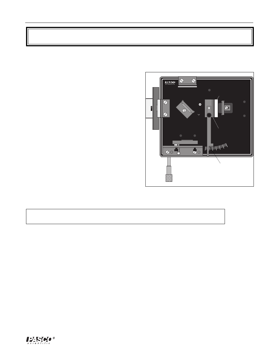
Figure 3.1. Equipment Setup
Read Angle of
Inclination on
Degree Scale
Rotational
pointer
Glass plate