Twyman-green mode 1, Fabry-perot mode 1, On its magnetic backing and position it – PASCO OS-9257A PRECISION INTERFEROMETER User Manual
Page 12: Remove the original lens (l, Until both sets of dots are the same size, Replace lens l, Figure 7. twyman-green mode setup, Figure 8. fabry-perot mode setup
Precision Interferometer
012-07137A
8
OS-9255A
PRECISION
INTERFEROMETER
-5
0
5
10
15
25
30
ADJUSTABLE MIRROR
MICHELSON, TWYMAN-GREEN
B
E
A
M
S
P
LIT
TE
R
M
IC
H
E
LS
O
N
C
O
M
P
E
N
S
AT
O
R
M
IC
H
E
LS
O
N
18 mm FL
LENS
VIEWING SCREEN
MICHELSON, TWYMAN-GREEN
1 div = 1 MICRON
OS-9255A
PRECISION
INTERFEROMETER
-5
0
5
10
15
25
30
ADJUSTABLE MIRROR
MICHELSON, TWYMAN-GREEN
BEAM
SP
LITTER
M
ICH
E
LSO
N
COMPENSA
TOR
M
ICHELSON
18 mm FL
LENS
VIEWING SCREEN
MICHELSON, TWYMAN-GREEN
1 div = 1 MICRON
Twyman-Green Mode
1.
Set up the interferometer in the Michelson mode, as
described above.
2.
Remove the pointer from the rotational componet
holder. (It is recommended to store the pointer, washer
and thumbscrew in the storage case.) Place the compo-
nent holder between the beam-splitter and the movable
mirror (see Figure 7). It attaches magnetically. Mount a
second 18 mm FL lens (L
2
) on its magnetic backing
and position it .
3.
Remove the original lens (L
1
) from in front of the laser.
Observe the two sets of dots on the viewing screen
one set from the movable mirror and one set from the
adjustable mirror. Adjust the position of L
2
until both
sets of dots are the same size.
4.
Adjust the tilt of the adjustable mirror until the two sets
of dots coincide.
5.
Replace lens L
1
in front of the laser. Move the viewing
screen so it's at least 12 inches from the edge of the
interferometer base. Fringes should appear in the bright
disk of the viewing screen. Fine adjustments of L
1
may be necessary to find the fringes. A piece of white
paper or cardboard can be used in place of the viewing
screen. A 48 mm FL convex lens may also be used to
magnify the projected image of the fringes.
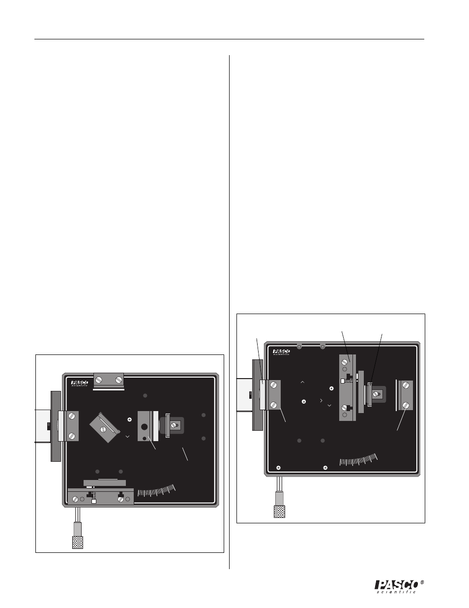
Fabry-Perot Mode
1.
Align the laser and interferometer base as described in
Laser Alignment at the beginning of this section. The
laser beam should be approximately parallel with the
top of the base, should strike the center of the movable
mirror, and should be reflected directly back into the
laser aperture.
2.
Mount the adjustable mirror where indicated on the in-
terferometer base and one component holder in front of
the movable mirror. See Figure 8.
3.
Place the other component holder behind the movable
mirror and attach the viewing screen to its magnetic
backing. You should see several images of the laser
beam on the viewing screen.
4.
Using the thumbscrews, adjust the tilt of the adjustable
mirror until there is only one bright dot on the screen.
5.
Now mount the 18 mm FL lens on the front compo-
nent holder. A clear sharp interference pattern should
be visible on the viewing screen. If you use light with
two component wavelengths, instead of a laser, two sets
of fringes can be distinguished on the viewing screen.
Lens
18mm FL
Figure 7. Twyman-Green Mode Setup
Rotational
component holder
Component
holder
Component
holder
Viewing screen
Adjustable mirror
Movable mirror
Lens
18mm FL
Figure 8. Fabry-Perot Mode Setup