PASCO PS-2128 Visual Accelerometer User Manual
Page 19
Visual Accelerometer
Model No. PS-2128
18
®
There is a ridge on the bottom of the case (Figure 1.12b) to help align
the clamps square to the case. Zero the Accelerometer in its vertical
orientation.
Additional equipment required: Visual Accelerometer Accessory
Kit (PS-2516)
Additional Equipment Recommended: Small Base and Support Rod
(SE-9451)
13) Visual Accelerometer Hanging
from a Rope (Free Fall)
For free fall studies, the bottom of the
Visual Accelerometer has a channel
that accepts a cord or a small rope. By
running the rope through a foam
cushion at the bottom, you can allow
the Accelerometer to free fall. Zero
the Accelerometer in its vertical
orientation.
Additional equipment
recommended: No bounce pad
(SE-7347)
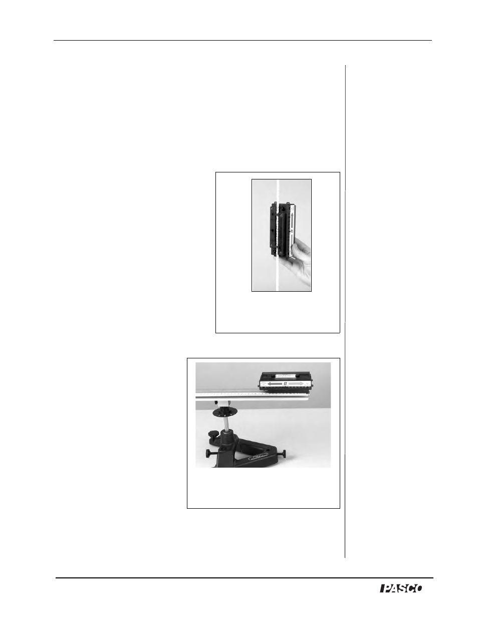
14) Visual Accelerometer on
Rotating Platform
The Visual Accelerometer
attaches to the Rotating
Platform for centripetal
acceleration studies. Use two
1/4-20 plastic thumbscrews
and two square nuts from the
Visual Accelerometer
Accessory Kit. The square
nuts fit into the T-slot (Figure
1.14) in the platform. You can
use either the slot in the top or
slot in the side. For the exact
center point of the sensor, see the Specifications in Appendix A.
Additional equipment required: Rotating Platform (ME-8951)
Figure 1.13: Visual
Accelerometer
threaded from a rope
Figure 1.14: Visual
Accelerometer rotating on a
platform