Setup options – PASCO PS-2128 Visual Accelerometer User Manual
Page 12
®
Model No. PS-2128
Visual Accelerometer
11
Setup Options
The Visual Accelerometer can be mounted in various ways for studies
of linear, rotary, and centripetal acceleration, elastic and inelastic
collisions, friction, free fall, etc. The following paragraphs and
photographs describe some sample experiment setup options.
If you plan to use the Visual Accelerometer in various orientations,
consider purchasing a Visual Accelerometer Accessory Kit (PS-2516).
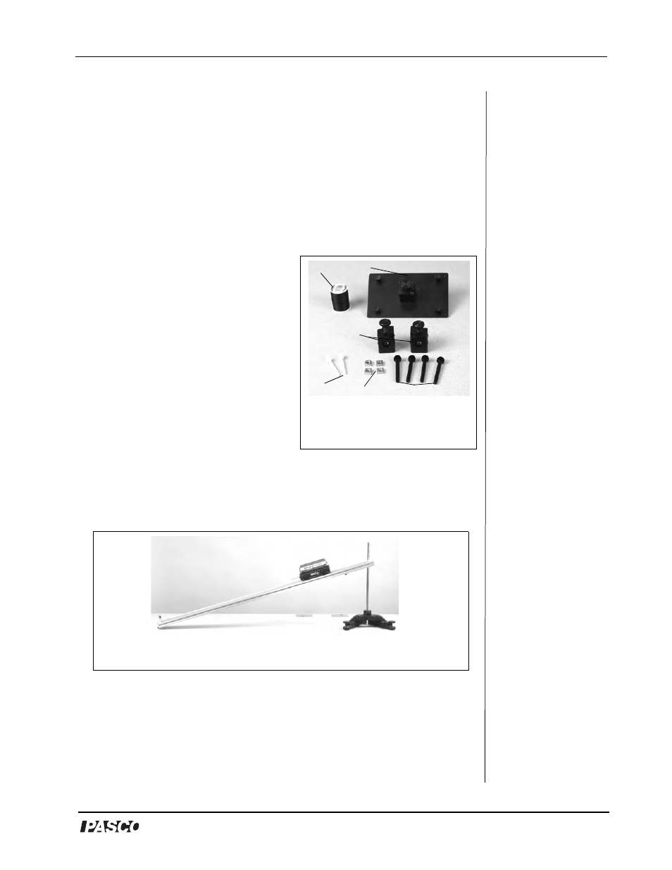
The Visual Accelerometer Accessory Kit includes the following:
1. Four String Pendulum Plate (1)
2. Plastic Rod Clamps (2)
3. M-5 plastic thumbscrews (2)
4. 1/4-20 plastic thumbscrews (4)
5. 1/4-20 square nuts (4)
6. Roll of thread (1)
1) Visual Accelerometer on an
Inclined Track
Use the Visual Accelerometer with a Dynamics Track to study
acceleration changes on an incline. With the thumbscrews provided
with the Accelerometer, attach the Visual Accelerometer to a PAScar
or a Dynamics Cart.
A gentle slope is best because it gives the student more time to observe
the change in acceleration. Zero the Accelerometer on the incline.
Release the cart from rest or launch upwards.
Additional equipment required: Dynamics Track [1.2 (ME-9435A)
or 2.2 m (ME-9458)], Dynamics Cart (ME-9430) or PAScar (ME-
6950), Large Rod Base (ME-8735) and Steel Rod (ME-8738)
1
Figure 1.0: Visual
Accelerometer Accessory
Kit
2
3
4
5
6
Figure 1.1: Visual Accelerometer and Cart on an inclined track