PASCO ME-9833 Physical Pendulum Set User Manual
Page 9
Physical Pendulum Set
Model No. ME-9833
9
®
2. Use calipers to carefully measure the
distance, L
cg
, from the center of gravity to
one of the other pivot points on the irregular
shape. Record the measurement as L
cg
, the
distance from the center of gravity to the
pivot point.
3. Replace the irregular shape on the Rotary
Motion Sensor by attaching it with one of the
mounting screws through the pivot point that
you used for the measurement.
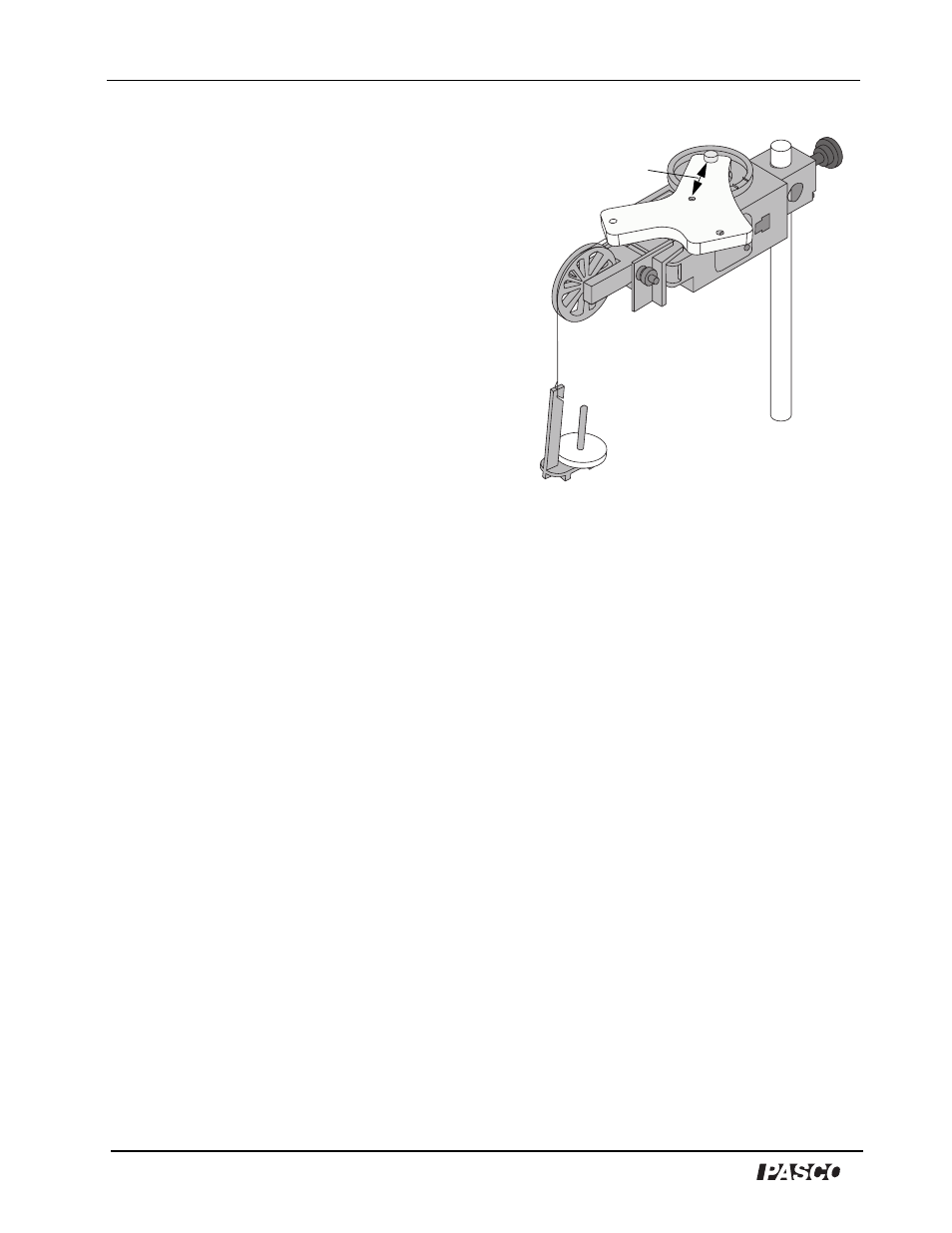
Data Recording: Parallel Axis
1. Wind the string about the step pulley so that the
mass hanger is just below the Super Pulley. Hold
the irregular shape in place.
2. Start recording data and then release the irregular shape so that it rotates freely.
3. Stop recording data when the mass hanger reaches its lowest point.
4. Repeat the process a total of three times.
Analysis: Parallel Axis
Find the moment of inertia about the parallel axis.
1. Use the same setup in the software to find the average angular acceleration.
2. Calculate the net torque (
τ = rm(g - rα)). Calculate the moment of inertia about the
parallel axis by dividing the net torque by the average angular acceleration
pivot
. Record
the results as the moment of inertia about the parallel axis, I
pivot
.
3. Calculate ML
2
cg
, the moment of inertia about the parallel axis of the irregular shape as if
all its mass is concentrated at its center of gravity. Use the distance from the pivot point to
the center of gravity as L
cg
.
4. Calculate the sum of I
cg
and ML
2
cg
. Compare the sum to the moment of inertia about the
parallel axis, I
pivot
.
5. Find the percent difference between I
pivot
and the sum of I
cg
and ML
2
cg
and record the
percent difference. Set up a graph display in the software of angular velocity versus time.
Extensions
Figure 1-2: Irregular
shape mounted
through a parallel axis
Measure L
cg