Introduction, Basic setups – PASCO ME-9833 Physical Pendulum Set User Manual
Page 4
®
Model No. ME-9833
Physical Pendulum Set
4
Introduction
The Physical Pendulum Set consists of six parts: pendulum bar (28 cm), offset hole, solid disk, thin
ring, thick ring, and irregular shape. This set of objects allows the study of physical pendula,
moments of inertia, and the parallel axis theorem. It includes six mounting screws for attaching the
physical pendula to a Rotary Motion Sensor in order to measure the object’s acceleration due to an
applied torque, or the object’s period of oscillation when the pendulum swings freely.
Basic Setups
Using the Rotary Motion Sensor to Measure Moment of Inertia
You can use the Rotary Motion Sensor (RMS) to measure the motion of a rotating object as it is
accelerated by a net torque. The ratio of net torque to angular acceleration is the object’s moment of
inertia.
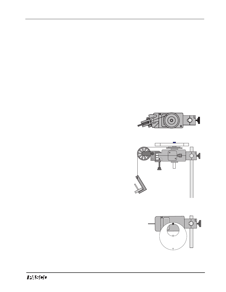
• Mount the Rotary Motion Sensor horizontally on a support
rod with the three step pulley on top.
• Arrange the three step pulley on the shaft on top of the sensor
so that the largest diameter step is nearest to the sensor.
• Mount a Super Pulley with Clamp to the platform area at the
end of the sensor opposite to the support rod.
• Connect a string to one of the steps on the three step
pulley and drape the string over the Super Pulley. Adjust
the angle of the Super Pulley with Clamp so that the string
is tangent to the step on the three step pulley (see Fig. 2).
• Put the object to be measured onto the shaft of the sensor
above the three step pulley. Secure it in place with one of
the mounting screws.
• Attach a mass hanger to the end of the string that is draped
over the Super Pulley.
Using the Rotary Motion Sensor to Measure Period of Oscillation
You can use the Rotary Motion Sensor to measure the period of
oscillation of the objects in the Physical Pendulum Set.
• Mount the Rotary Motion Sensor horizontally on a support rod so
that the three step pulley is on one side (oriented vertically).
• Remove the mounting screw and the three step pulley.
• Use a mounting screw to attach the object to be measured to the
shaft of the sensor.
Figure 1: Top view - Adjust the
angle of the Super Pulley.
Figure 2: Moment
of Inertia setup
Figure 3: Period of
oscillation setup
Object