Diamond Products CG-2 Mini Groover User Manual
Page 12
Inspecting the Blade
Always inspect each blade prior to blade
installation. DO NOT use damaged blades for
cutting in order to avoid injuring yourself, others,
or the machine. Discard all damaged blades and
inspect each replacement blade for deficiencies.
Inspect blades prior to installation for:
• Cracks, Nicks, Or Dents
• A damaged and/or deformed arbor.
• Darkness or discoloration near edges of the
blade.
• A deformed blade circumference.
• Segments missing or cracked.
• Core wear.
• Bending or warpage.
• Uneven side widths.
Blade Speed
Refer to the Diamond Products blade specification
for information on the recommended blade RPM
when cutting. DO NOT use a blade with a lower
maximum operating speed than the blade shafts
speed when cutting.
Blade Shaft Removal
• DO NOT remover or install a
blade shaft with the engine
running.
• Failure to properly secure the
loose flange and blade shaft tie bolts may
cause parts to loosen and fall off.
• The blade shaft assembly weighs up to 500
pounds and must be lifted to a vertical
position to change blades.
• Failure to follow these instructions may
cause serious injury or death.
• Always wear protective gloves
when handling blades.
• Always let blades cool prior to
removing or replacing of
blades.
1. Remove the belt guard. There are 6 bolts
that must be removed using a 9/16”
Wrench or Socket.
2. Remove the blade shaft drive belts (2).Refer
to page __ for removal and installation.
3. Lower the saw until the blades make
contact with the ground using the lowering
button located on the right side of the
control handle.
4. Block the front and rear of the blade shaft
assembly with wooden block or similar to
ensure the blade shaft assembly does not
roll when bearing bolts are loosened.
5. Remover the depth stop wheels off the
front of the machine by removing the hex
nuts with a 1.50” wrench or socket.
6. Loosen and remover the 4 blade shaft
bearing bolts using a 3/4” wrench or socket.
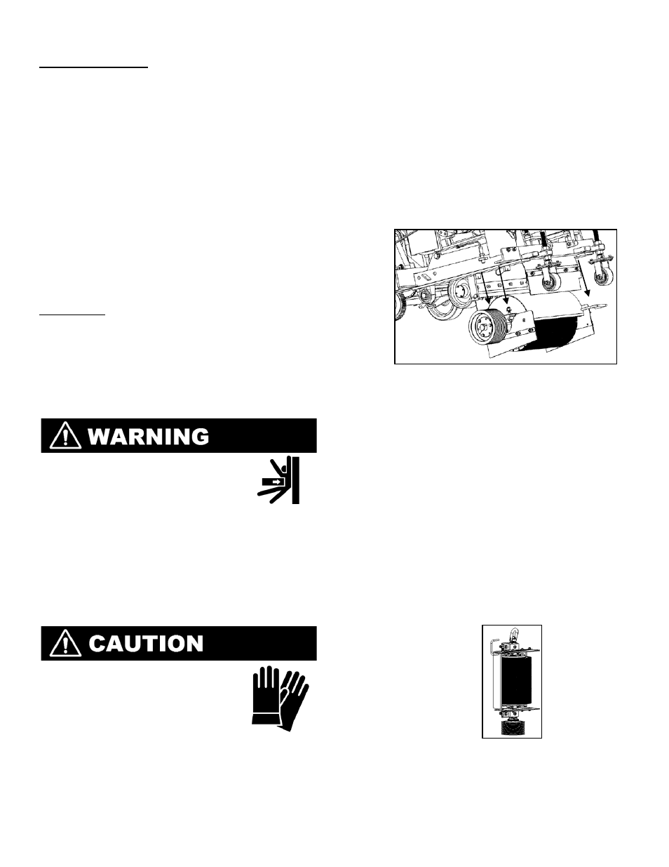
Carefully Lower Blade Shaft Assembly From Machine
7. Slowly raise the saw to the maximum height
using the raise (Left) pushbutton on the
speed lever.
8. Carefully remove chock blocks at the front
of the blade shaft assembly and slowly
remove the assembly, it should clear the
machine.
9. Using supplied hoist ring (2504720)
attached to the non sheave end of the
blade shaft. Make sure the ring is fully
seated in the threads and that threads are
clean and free of debris on the end of the
blade shaft. With a suitable lifting device
and proper capacity chain or cable, lift the
shaft and carefully set down on sheave end.
After securely setting in upright position,
remove hoist ring.
Place Blade Shaft Assembly on End Using Hoist Ring
10. Remove the revolving blade shield by
removing the hex head machine screws
located on the underside of the shield near
the bearings.
10