6 built-in output connections – Micromod RetroPAK: SLC Installation Manual User Manual
Page 57
SLC RetroPAK Controller
POWER, GROUNDING, AND BUILT-IN I/O CONNECTIONS
33
3.6
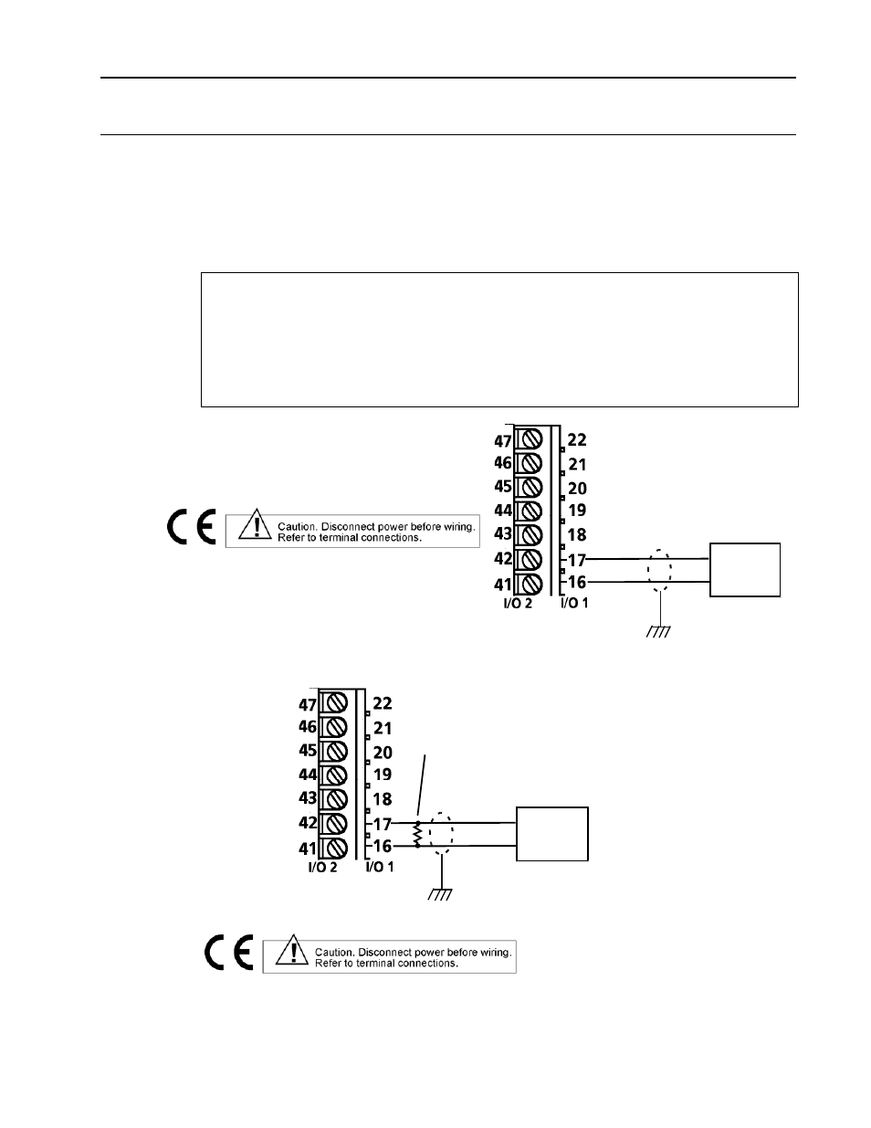
BUILT-IN OUTPUT CONNECTIONS
Built-in outputs 1 and 2 are milliamp analog control outputs. Connections to these outputs
are made as shown in Figure 3-2. The output circuit diagrams, Figures 3-8 and 3-9 identify
the Output 1 terminals as I/O 1 and the Output 2 terminals as I/O 2.
The built-in outputs are always milliamp signals. When an application requires a voltage
signal, a precision dropping resistor must be connected across the output terminals to
generate the required voltage as shown in Figure 3-9.
Specifications for built-in outputs 1 and 2 are:
Range: 0 to 20 mA maximum, non-isolated
Resolution: 14 microamps
Accuracy: ±0.2% of setting or 14 microamps, whichever is greater
Temperature Effect: 0.01% per °C or 1 microamp per °C , whichever is greater
Load Resistance: 1000 ohms maximum at 22 mA
at 54 mA: 400 ohms maximum
Open Circuit Voltage: 25.5 volts typical
Ripple: 20 millivolts peak to peak at 100K Hz typical
-
+
Output
Receiver
to Chassis
Terminal
Figure 3-8. Built-in Milliampere Output Connections
-
+
Output
Receiver
Precision Dropping Resistor
Typical Value: 500 ohms ±0.01% (less than 10ppm)
Maximum Value: 1000 ohms
Note:
For 0 to 10 Vdc signal to the receiver, controller output
current range must be set at 0 to 20.0 mA dc when using
500 ohm resistor.
to Chassis
Terminal
Figure 3-9. Built-in Voltage Output Connections