2 built-in rtd input – Micromod RetroPAK: SLC Installation Manual User Manual
Page 53
SLC RetroPAK Controller
POWER, GROUNDING, AND BUILT-IN I/O CONNECTIONS
29
3.5.2
Built-In RTD Input
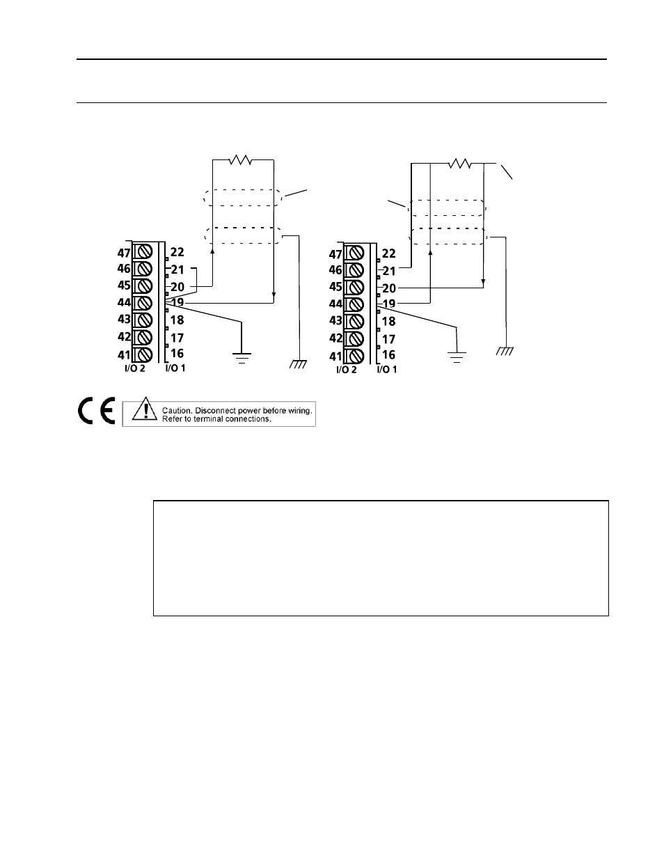
Make RTD input connections as shown in Figure 3-4. See Section 4.3.6 for a listing of
materials, standards and sample RTDs supported by the instrument software.
Shield
2-WIRE RTD
t°
to Chassis
Terminal
3-WIRE RTD
Shield
to Chassis
Terminal
Note:
4-Wire RTD
connected same
as 3-Wire RTD with
fourth lead unused
t°
to instrument
ground
to instrument
ground
Figure 3-4. Built-in RTD Input Connections
RTD input specifications are:
RTD Type: 3-Wire or 2-Wire
Range: Configurable
•
Normal Range: 0 to 430 ohms
•
Low Range: 0 to 55 ohms
Resolution: less than 0.004 ohms
Accuracy: ±0.05% of input resistance or 0.1 ohms whichever is greater
Temperature Effect: ±0.01% per °C or 0.01 ohms per °C whichever is greater
RTD Current: 250 microamps typical
Burnout Detection: Reading goes upscale when any lead opens