Micromod RetroPAK: SLC Installation Manual User Manual
Page 52
SLC RetroPAK Controller
POWER, GROUNDING, AND BUILT-IN I/O CONNECTIONS
28
3.5.1
Built-In Voltage, Millivolt and Thermocouple Inputs
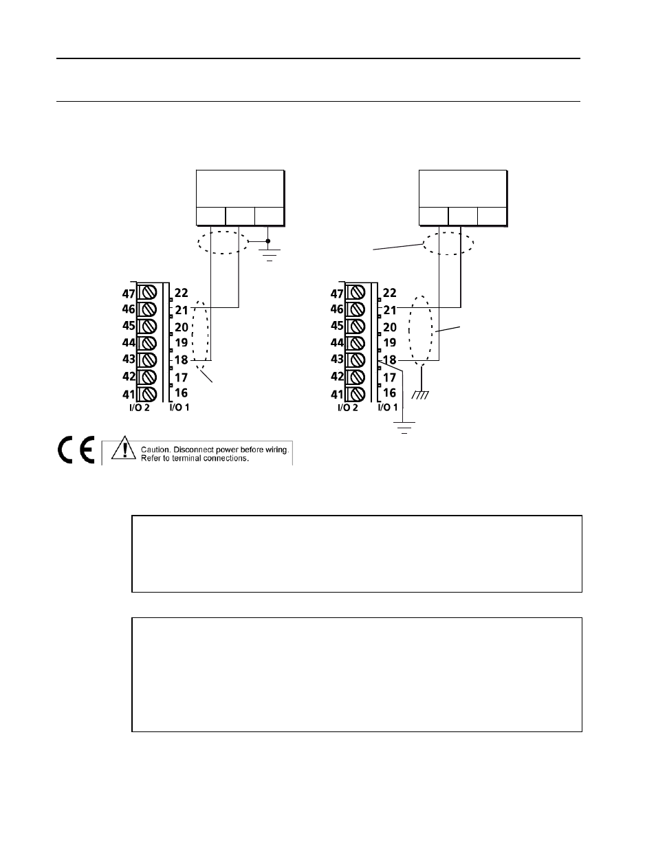
Make volt, millivolt and thermocouple input connections as shown in Figure 3.3. Always
connect the first thermocouple input to the I/O 1 terminals to enable automatic cold junction
compensation for all thermocouple inputs.
GROUNDED
Shield to be left
unconnected at this end.
V, mV or tc
Source
UNGROUNDED
V, mV or tc
Source
-
+
G
Shield to be left
unconnected at this end.
-
+
G
Red wire for
Tc Input
to Chassis
Terminal
to instrument
ground
Figure 3-3. Built-in Voltage, Millivolt and Thermocouple Input Connections
Volt input specifications are:
Input Range: –10 mV to +6 Vdc
Input Impedance: 10M ohms minimum
Resolution: less than 50 microvolts
Accuracy: 0.05% of input or 100 microvolts, whichever is greater
Temperature Effect: 0.01% per °C or 10 microvolts per °C, whichever is greater
Burnout Detection: Reading goes downscale when any lead opens.
Millivolt and Thermocouple input specifications are:
Input Range: –10 to 120 mVdc
Temperature range limits for thermocouple inputs: See Table 4-1
Input Impedance: 10M ohms minimum
Resolution: less than 1 microvolt
Accuracy: 0.08% of input or 20 microvolts, whichever is greater
Temperature Effect: 0.01% per °C or 1 microvolt per °C, whichever is greater
Burnout Detection: Configurable for thermocouple inputs and millivolt signals which
represent thermocouple inputs. Choices are upscale or downscale
excursion of reading when any lead opens, or no detection.