Micromod RetroPAK: SLC Installation Manual User Manual
Page 22
SLC RetroPAK Controller
MODULAR I/O CONNECTIONS
38
4.3.2
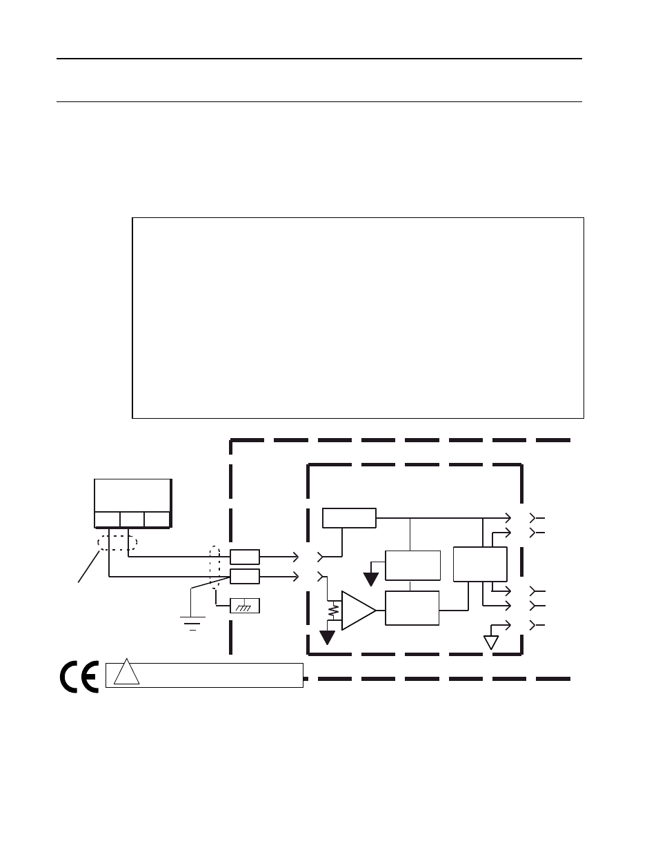
2012A Current Inputs (VCIM)
Make current input connections as shown in Figure 4-5 for 2-Wire Transmitter (2012A).
2-Wire Transmitter (2012A)
The 2-wire version of the milliampere input receives its loop current from a 24V dc current
supply built into the module. This current supply is automatically connected in the circuit
when the 2-wire input connection is made. The load on the transmitter is nominally 100
ohms. Due to heat generated, this module must be installed in a location with no adjacent
module on either side. Input specifications are:
ANALOG INPUT (CURRENT WITH 2-WIRE TRANSMITTER POWER)
Range: (0-100%) 4 to 20mA
Low limit: 0 mA
Upper limit: 27.5 mA
Input Resistance: 50 ohms
Noise filter: 3 db at 5 Hz
Resolution: 14 bits
Sensitivity: 1 uA
Accuracy (calibrated): ±0.2% of span
Two Wire Excitation Supply
Open circuit voltage: 24V ±5%
Short circuit current: maximum at 38 mA
Isolation : 250 Vrms
Max Survivable Input: ±300 Vdc or 250 Vac (Differential)
Common mode rejection: 100 db at 60 Hz minimum
Normal mode rejection: 40 db at 60 Hz minimum
S1
CONTROLLER
4 to 20
mA dc
+
39
40
A/D
2012A CURRENT INPUT
MODULE (Module Location S1)
Processor
Input
Isolation
+24V Iso
DATA
SEL
CLK
GND
+5V dc
3
6
4
7
5
2
1
+10V Iso
Note: For other module locations, see
Figure 4-1 for terminal numbers.
2-Wire
Transmitter
-
+
G
Shield to be left
unconnected at
this end.
-
Caution. Disconnect power before wiring.
Refer to terminal connections.
!
to instrument
ground
Figure 4-3. Typical Connections for a 2012A Current Input Module with 2-Wire Transmitter Power