Micromod RetroPAK: SLC Installation Manual User Manual
Page 51
SLC RetroPAK Controller
POWER, GROUNDING, AND BUILT-IN I/O CONNECTIONS
27
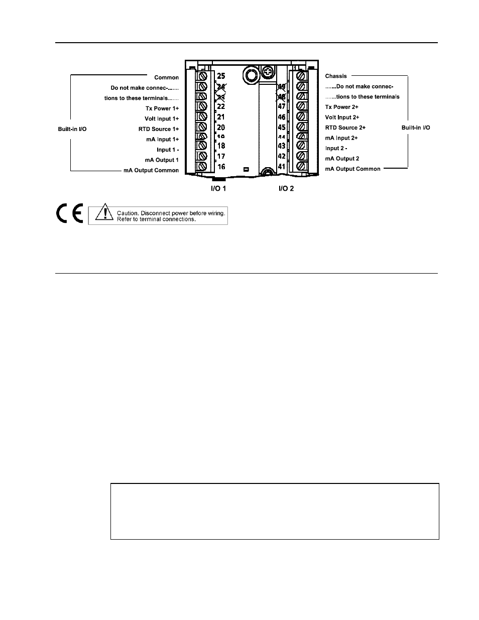
Figure 3-2. Terminal Identifications for Built-in I/O
3.5
BUILT-IN PROCESS INPUT CONNECTIONS
Built-in inputs 1 and 2 are isolated universal analog inputs which accept volts dc, millivolts dc,
milliamps dc (includes 2-wire transmitters), RTD, Thermocouple, and resistance signals.
Connections to these inputs are made to the terminals shown in Figure 3-2. The input circuit
diagrams in this section (Figures 3-3 to 3-9) identify Input 1 terminals as I/O 1 and Input 2
terminals as I/O 2.
Each of the two built-in analog input circuits is isolated from every other circuit. It is
recommended that either the Input– or the mA Input + terminal be connected to ground at
some point in the system to prevent possible buildup of static electricity and reduce the
pickup of noise.
The input circuit and input signal specifications for each input type are shown in the following
sections:
• Volt, Millivolt and Thermocouple Input - Section 3.5.1
• RTD Input - Section 3.5.2
• Current Input from a 2-Wire Transmitter - Section 3.5.3
• Current Input from a Non 2-Wire Transmitter - Section 3.5.4
• Resistance Input - Section 3.5.5
General specifications for built-in process inputs are:
Input Isolation: Galvanic isolation using transformers and optical isolators.
Input Common Mode Rating: 45V dc
Common Mode Rejection: 120 dB @ 50/60 Hz
Normal Mode Noise Filter: 20 dB minimum @ 60 Hz
Maximum Normal Mode Voltage: 30V dc (except current input)
Display Accuracy: Input accuracy ± one least significant display digit