Micromod Micro-DCI: 53ML5100 Manual Loader User Manual
Page 6
53ML5100B Manual Loader
INSTRUCTION MANUAL
vertical axis. Also, the vertical axis has a numeric range (zero and span). An input channel tag name appears
in the upper left corner of the display. A digital readout for the analog output channel appears under the
letters SP in the upper half of the display. The analog input measured units tag appears in the middle of the
display and beneath it a digital readout appears under the letters PV. These two displays provide quick
recognition of the output level relative to the process variable.
As shown in Figure 1-2, the Manual Loading Station contains a graphical dot matrix display; horizontal and
vertical keypads; a MINI-DIN configuration port connector concealed behind the front panel pull-down door;
terminals for signal input/output wiring and power wiring; and a compact instrument case that protects the
instrument main printed circuit board and internal power supply.
The display is a 96 X 48 gas discharge dot matrix, contrasted orange-on-black to enhance visibility and ease
of reading. The intensity is a range selectable entry from 0 to 7, with 0 being the brightest setting (see Table
4-6).
To the right of the display is the vertical keypad and directly beneath the display is the horizontal keypad.
Both keypads have functioning push buttons that are dependent on the instrument mode of operation which
can be either operator mode or engineering mode. Mode selection is made with the Mode ( z) push button
on the horizontal keypad. Engineering mode is entered to make the necessary selections for the operator
displays; otherwise, the instrument is left in operator mode for process applications. Both keypads are
described as follows:
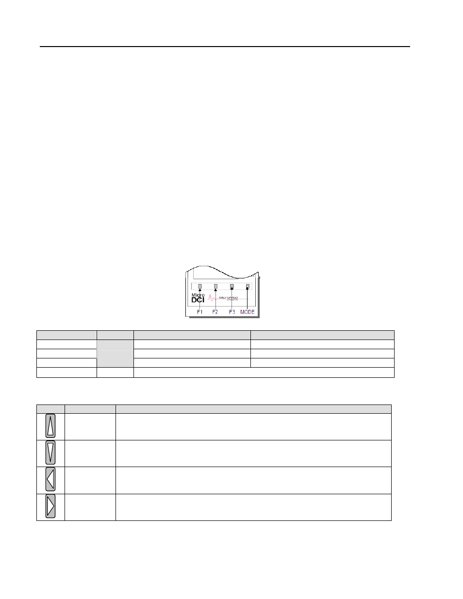
Horizontal Keypad
Push Button Title
Operator Mode
Engineering Mode
F1
Page back to previous display.
Back to previous entry line function.
F2
Page forward to next display.
Pages the configure/display functions.
F3
xecutes an enter or display function.
Moves Quad Bargraph pointer.
E
Mode
Operator/Engineering mode select
Vertical Keypad
Title
Engineering Mode
Ascending
Character
haracter, number, or symbol
Select
For engineering mode only - displays one character at a time in ascending
alphanumeric order; is released when the desired c
appears on the engineering mode data entry line.
Descending
er
haracter, number, or symbol
Charact
Select
For engineering mode only - displays one character at a time in descending
alphanumeric order; is released when the desired c
appears on the engineering mode data entry line.
Decrease
Output/
Shift Left
In operator mode - decreases the selected channel analog output.
In engineering mode - shifts the selected character one position left on the
engineering mode data entry line each time it is pressed.
Decrease
Output/Shift
Right
ing mode data
entry line one character position right each time it is pressed.
In operator mode - it increases the selected channel analog output.
In engineering mode - it shifts the characters on the engineer
2