3 displays and push buttons, 1 operator displays, Displays and push buttons – Micromod Micro-DCI: 53ML5100 Manual Loader User Manual
Page 23: Perator, Isplays
53ML5100B Manual Loader
INSTRUCTION MANUAL
19
3 DISPLAYS AND PUSH BUTTONS
This section provides illustrations with item call-outs of the six operator displays and engineering mode
overlays. Where applicable, datapoints are identified parenthetically with the display item call-outs. The
datapoints are defined in Section 4. The front panel push button definitions are repeated in this section from
Section 1, because they are used in the engineering mode display overlay examples to enter a key password,
display a datapoint, and alter a datapoint.
3.1 Operator Displays
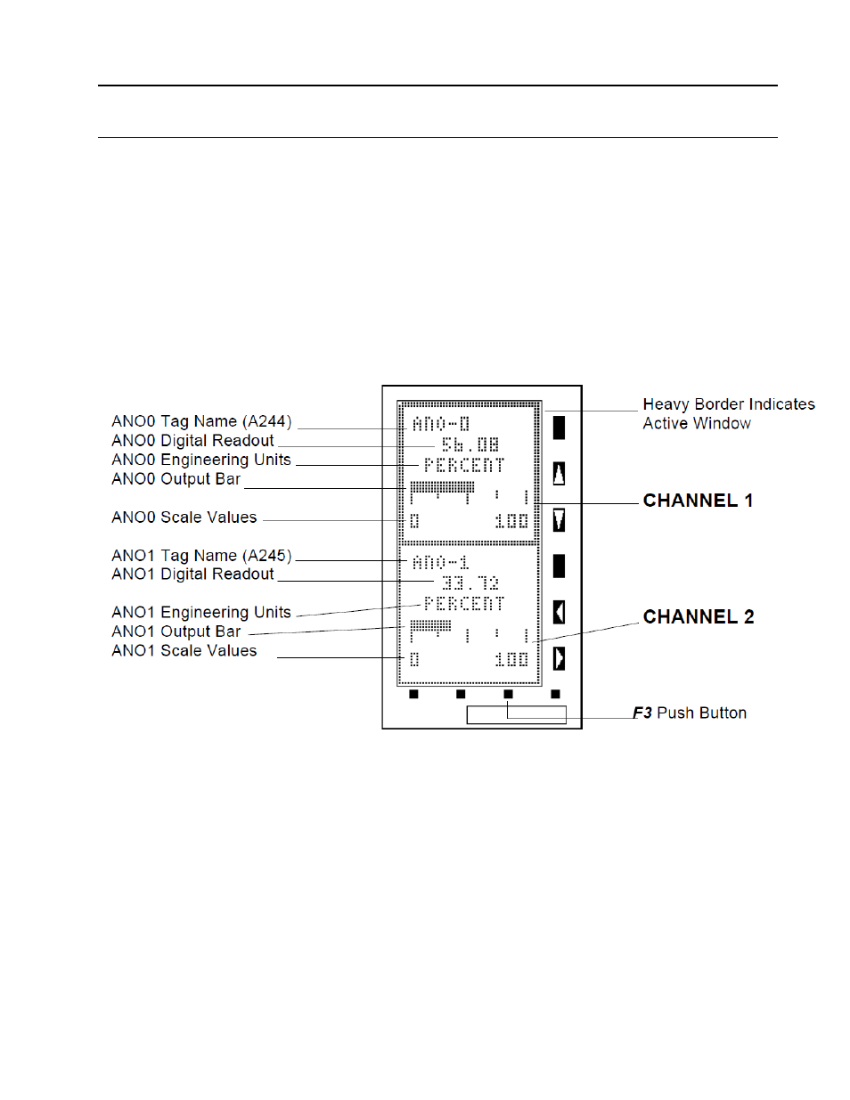
Display 1 - Dual Channel Manual Loader (Chs. 1&2) is illustrated twice: in Figures 3-1 and 3-2 to show
channel 1 selected for output control and channel 2 selected for output control using the F3 push button. The
remaining five operator displays are illustrated in Figures 3-3 through 3-7 as follows: Figure 3-3, Display 2 -
Single Channel Manual Loader (Ch. 1 only); Figure 3-4, Display 3 -Manual Loader with Analog Input (Ch. 1);
Figure 3-5, Display 4 - Manual Loader with Analog Input (Ch. 2); Figure 3-6, Display 5 - Analog Input Indicator
with Setpoint Display (Ch. 1); and Figure 3-7, Display 6 - Analog Input Indicator with Setpoint Display (Ch. 2).
Figure 3-1. Display 1 - Dual Channel Manual Loader (Chs.
1&2)