3 altering a datapoint, Altering a datapoint – Micromod Micro-DCI: 53ML5100 Manual Loader User Manual
Page 31
53ML5100B Manual Loader
INSTRUCTION MANUAL
3.3.3 Altering a Datapoint
The procedure in Table 3-3 illustrates how to alter the contents of datapoint C175, which
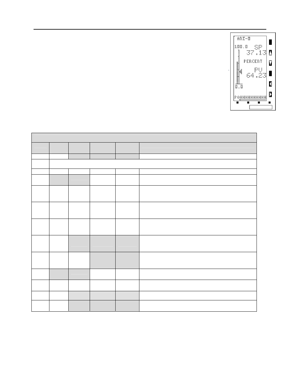
is ANI2 Alarm Limit 1, from 80 to 90. Figure 3-10 is provided to show the maximum input
character length for the engineering mode edit line. The edit line can accept ten
characters. The full ten character field is used primarily for the A type datapoint text
strings (tag names). Reference Table 4-1 in Section 4
f
or information about the datapoint
types. Note that in Figure 3-10, the PO is residual from the prompt POINT and that the
character field string starts with 1 and ends with 0 (underlined in the figure) to illustrate 10
characters.
Figure 3-10. Entry Line
Ten Character Field
Table 3-3. Procedure to Alter a Datapoint
Step
Press
Once
Shift
Result
Press to
Locate
Target
Char.
Result
1
Puts instrument in engineering mode.
2
If CONFIGURE does not appear, press F2.
3
F3
Displays entry line: POINT
4
C
Puts C on entry line: POINT .C
5
.CΔ
1
Shifts C and puts 1 on entry line:
POINT .C1
6
.C1Δ
7
Shifts C1 and puts 7 on entry line:
POINT .C17
7
.C17Δ
5
Shifts C17 and puts 5 on entry line:
POINT .C175
8 F3
Enters address to display datapoint contents.
The address with the contents are displayed as
follows: C175 80.0000
9
Hold
•
locator
C175 contents shifted right; only the locator
point remains on the entry line: C175
10
9
Puts 9 on entry line: C175 .9
11
.9Δ
0
Shifts 9 and puts 0 on entry line:
C175 .90
12 F3
Enters the value 90 in datapoint C175
13
Returns instrument to operator mode.
NOTE:
Δ indicates Space
27