Max Machinery 121 INDICATOR User Manual
Page 31
121-000-350 © 2001 Max Machinery, Inc.
Pg 31
ENTER
ENTER
ENTER
ENTER
ENTER
ENTER
ENTER
ENTER
ENTER
ENTER
ENTER
ENTER
ENTER
ENTER
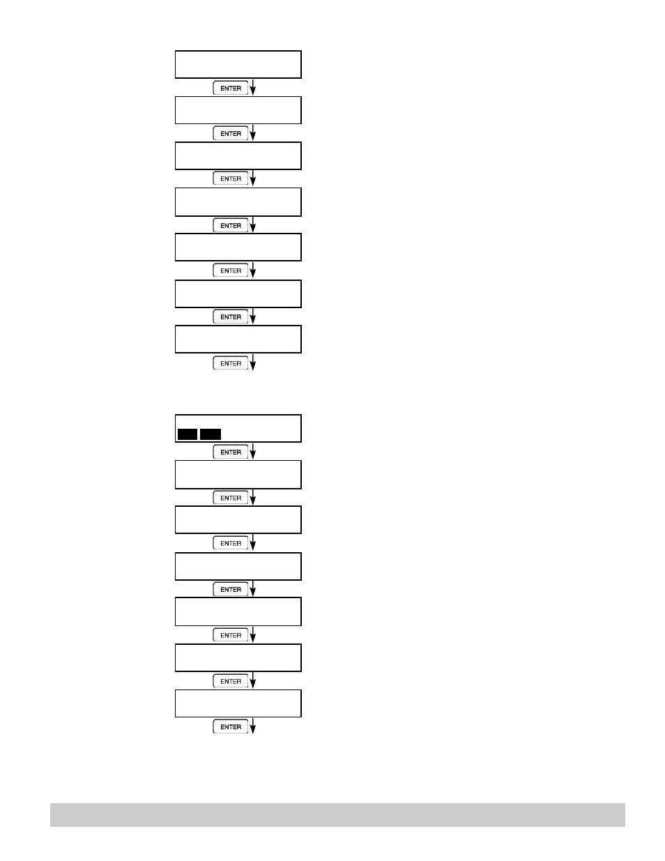
6.4.14
SETUP
ANALOG OUTPUT
6.4.15
SETUP RELAYS
(Relay 1 & Relay 2)
NOTE:
In Batch mode, Relay 1
is reserved for Preset,
Relay 2 is reserved for
Prewarn.
SETUPANALOG OUTPUT
ANALOG OUTPUT U S A G E
Rate Total Temp Dens
ANALOG OUTFLOW T Y P E
Vol CVol/Mass
ANALOG OUTPUT R A N G E
4-20mA
0-20mA
LS ANALOG OUTPUT
####### gal/m
FS ANALOG OUT 20mA
####### gal/m
ANALOG OUT DAMPING
0.0
Advance To
SETUP RELAYS
SETUP RELAYS
Rly1 Rly2
Rly3 Rly4
RELAY 1 USAGE
RATE TOTAL
NA
RELAY 1 DELAY
sec
0
RELAY 1 MODE
LO_ALARM HI_ALARM
RELAY 1 DURATION
#####
RELAY 1 SETPOINT
####### gal
RELAY 1 HYSTERESIS
##### gal/m
Press ENTER when Analog is flashing to setup the
Analog Output.
Select the desired Analog Output Usage.
Only if Rate selected & Flow EQ. = Mass, Cor/Vol
Select the desired Analog Output Flow.
Select the desired current range for the Analog Output.
Enter desired Analog Output Low Scale Value.
NOTE: Units label will correspond with output usage
type selected.
Enter desired Analog Output Full Scale Value.
Enter the desired Analog Output Damping Constant.
Select the desired Relay for setup.
(Relays 3 & 4 Optional)
If Relay 1 or Relay 2 Selected,
Select Rate, Total or NA.
If Rate selected, enter desired relay activation delay
value.
Select the desired Relay Activation.
Low:
Relay activates when reading is below setpoint.
High:
Relay activates when reading is above setpoint.
If Total Selected, Enter desired Relay Duration.
Enter the desired Setpoint. The Setpoint can be edited in
run mode using the PRE 1 key (PRE 2 key for Relay 2).
If Rate, selected, Enter desired Relay Hysteresis.