Optical – Luminex 100E Hardware User Manual User Manual
Page 23
x
MAP Technology
Luminex 100E Analyzer Overview
PN 89-00002-00-013 Rev. D
3 - 11
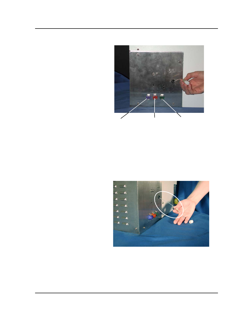
1. Nonpressurized Sheath Fluid Connector (Blue)
2. Waste Fluid Connector (Orange)
3. Pressurized Sheath Fluid Connector (Green)
Figure 10. Regulated Flow Sheath Supply
Sample Input Tube
The sample input tube provides the sample fluid interface between
the sample probe from the host system to the Luminex 100E
analyzer. This sample input tube aspirates sample.
Figure 11. Sample Input Tube (Without Cap)
Optical
The optical system consists of the optical assembly and the excitation
lasers. The optical assemblies do not require manual adjustment by
the user.
3
1
2