Reassembling the meter – Liquid Controls M-MA Meters User Manual
Page 20
reassembling the Meter
to complete meter reassembly:
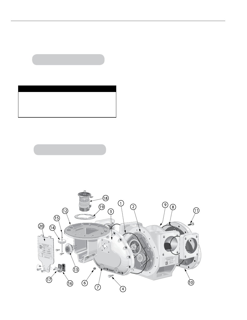
1. Push the O-ring (1) into the groove (2) on the front of the
meter housing.
2. Fasten the front cover (3) to the housing with the cover
screws (4) using the cover socket or open end/box end
wrench.
3. Screw the front drain plug (6) into the front drain plug hole
(7) using the drain plug allen wrench.
4. Push the O-ring (8) into the groove (9) on the rear of the
meter housing.
5. Fasten the rear cover (10) with the cover screws (11)
using the cover socket or open end/box end wrench.
6. Screw the rear drain plug (not shown) into the rear drain
plug hole using the drain plug allen wrench.
Meter Assembly Exploded View
reasseMblInG the Meter
LC recommends tightening the front and rear cover screws
in a criss-cross or “star” pattern with a minimum of two
passes. First pass should be at half-torque. Final pass(es)
should be at full torque. This method will ensure uniform seal
compression on cover O-ring or gasket. See page 21.
Tightening Front and Rear Covers
M-60 and M-80 models use a flat gasket.
M-60 and M-80 models use a flat gasket.
7. Screw the counter bracket (12) onto the front cover using
the counter bracket screws.
8. Insert the packing gland assembly (13) through the
counter bracket and into the cover plate. Make sure the
forks of the packing gland drive are in the slots of the
packing gland driver attached to the blocking rotor gear.
9. Screw the packing gland retaining plate onto the
counter bracket using the two retaining plate screws.
See Servicing the Packing Gland on page 15 for more
information.
10. Return the adjuster drive gear (14), the adjuster drive
shaft (15), and the drive shaft bushing (16) to the inside
of the counter bracket. Make sure the drive gear is in its
original position. See Reversing the Meter Registration on
page 10 for more information.
11. Screw the retaining spring (17) over the drive shaft
bushing and slide the retaining ring back into the slot on
the drive shaft.
12. Screw the standard adjuster (18) onto the adjuster
mounting plate (19).
13. Insert the standard adjuster and adjuster mounting plate
through the top of the counter bracket and onto the
adjuster drive shaft. Screw the mounting plate onto the
counter bracket.
14. Screw the dust cover onto the counter bracket using the
dust cover screws.
20