Reassembling the meter – Liquid Controls M-MA Meters User Manual
Page 19
reasseMblInG the Meter
Rotor Keys
reassembling the Meter
to reassemble the bearing plates and rotors:
continued from following page
4. The rotors should have a small amount of end-play and
be easy to turn. Test each rotor, one at a time. Turn the
rotors to make sure that they revolve freely. Jog the rotors
from end to end to check for end-play. If they do not move
easily in both tests, remove the rotors and check for
burrs and corrosion deposits. Clean them thoroughly and
repeat steps 2, 3 and 4.
5. Each rotor has a notch, or “keyway”, to hold a rotor key.
The rotor key is a small wedge of metal. Press a rotor
key into the keyway of each rotor with your thumb and
forefinger.
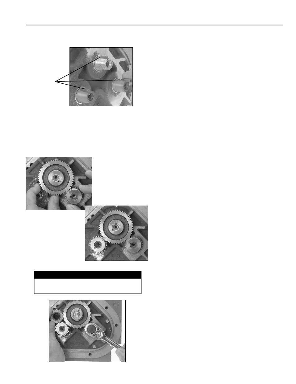
to time the rotor gears:
1. Slide the blocking rotor gear over the tapered blocking
rotor end and turn it until the timing mark is in position
to line up with the timing mark on the right displacement
rotor gear. Slide the right displacement rotor gear over
the tapered end of the rotor so that the timing mark lines
up with the blocking rotor gear timing mark.
2. Turn the blocking rotor gear (turn the right displacement
rotor gear with it) until the timing mark is in position to
line up with the timing mark on the left displacement
rotor gear. Slide the left displacement rotor gear over the
tapered end of the rotor so that the timing mark lines up
with the blocking rotor gear timing mark.
3. Position the spare displacement rotor gear between
the left displacement rotor gear and the blocking rotor
gear to prevent the gears from moving. Attach the right
displacement gear washer and screw using the rotor gear
wrench.
4. Keep the spare displacement rotor gear positioned by the
left displacement rotor gear. Attach the left displacement
gear washer and screw using the rotor gear wrench.
5. Position the spare displacement rotor gear between the
right displacement rotor gear and the blocking rotor gear.
Attach the blocking rotor gear with the packing gland
driver and screw using the rotor gear wrench.
6. Rotate the gears to make sure that the rotors turn freely.
Burrs, foreign material, or marred surfaces can restrict the
rotor movements. If the rotors do not turn freely, remove
the gears and rotors and deburr and clean the surfaces
again.
tIMInG the rotor Gears
Before putting the meter into service, the rotors must be timed. Rotors are timed by lining up timing marks stamped
onto the face of the gears. The timing mark on the blocking rotor gear is stamped on a gear tooth. The timing mark on
the displacement rotor gears is stamped on a space between two gear teeth. You may need to remove the gears and
reposition them several times to line up the timing marks correctly.
Tighten the gear screws to the torque specification
listed in the Torque Chart on page 22.
Torque the Gear Screw
19