Reversing the meter registration – Liquid Controls M-MA Meters User Manual
Page 10
reversInG the Meter reGIstratIon
The direction of flow is specified by the customer when the meter is ordered. The standard direction of flow, facing the
front of the meter, from left to right. A red tag labelled “inlet”, affixed to the meter before shipment, indicates the inlet
side of the meter.
If the meter is equipped with a strainer, air eliminator, and/or valve, each component must be moved to the correct
side of the meter when reversing the direction of flow. The strainer and air eliminator should always be located on the
inlet side of the meter. Valves should always be located on the outlet side of the meter. Some parts of the valve may
require repositioning. See the valve’s manual for more information.
When the meter is first installed, check the register. If the register counts down, meaning that the register numbers
decrease rather than increase, you must reverse the position of the adjuster drive gear.
To reverse the drive to the register, the position of the adjuster drive gear relative to the pinion gear of the packing
gland must be flipped.
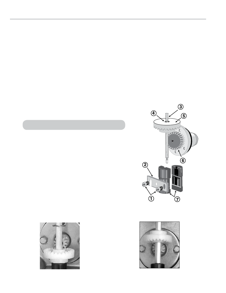
to reverse the meter registration:
1. Remove the dust cover. See Removing the Dust Cover on page 13.
2. Remove the retaining ring (4) with a screwdriver or pliers.
3. Remove the two retaining spring screws (1) with a standard
screwdriver.
4. Remove the retaining spring (2).
5. Remove the drive shaft (3) with the adjuster drive gear assembly
including (4) Retaining Ring and (5) Adjuster Drive Gear.
6. Remove the adjuster drive gear (5) and turn it 180° so that it is upside
down from the original installation position. The bushing (7) supports
the adjuster drive gear in the lower position. The retaining ring (4)
supports the adjuster drive gear in the upper position.
7. Reassemble the parts in reverse order. Make sure that the adjuster
drive gear meshes with the packing gland’s pinion gear (6) without
being too tight. There should be a little play in the gear teeth. The
retaining ring (4) should be placed in the groove provided on the drive
shaft (3), regardless of the adjuster drive gear position. The packing
gland pinion gear to adjuster drive gear ratio is either 1:1 or 2:1. In the
2:1 ratio, the pinion of the packing gland is smaller in diameter.
Adjuster drive gear engaged at top
Adjuster drive gear engaged at bottom
For M-15, M-25, M-30, and M-40 models, loosen the single set screw.
10