Servicing the drive components, Warning, Removing the dust cover – Liquid Controls M-MA Meters User Manual
Page 13
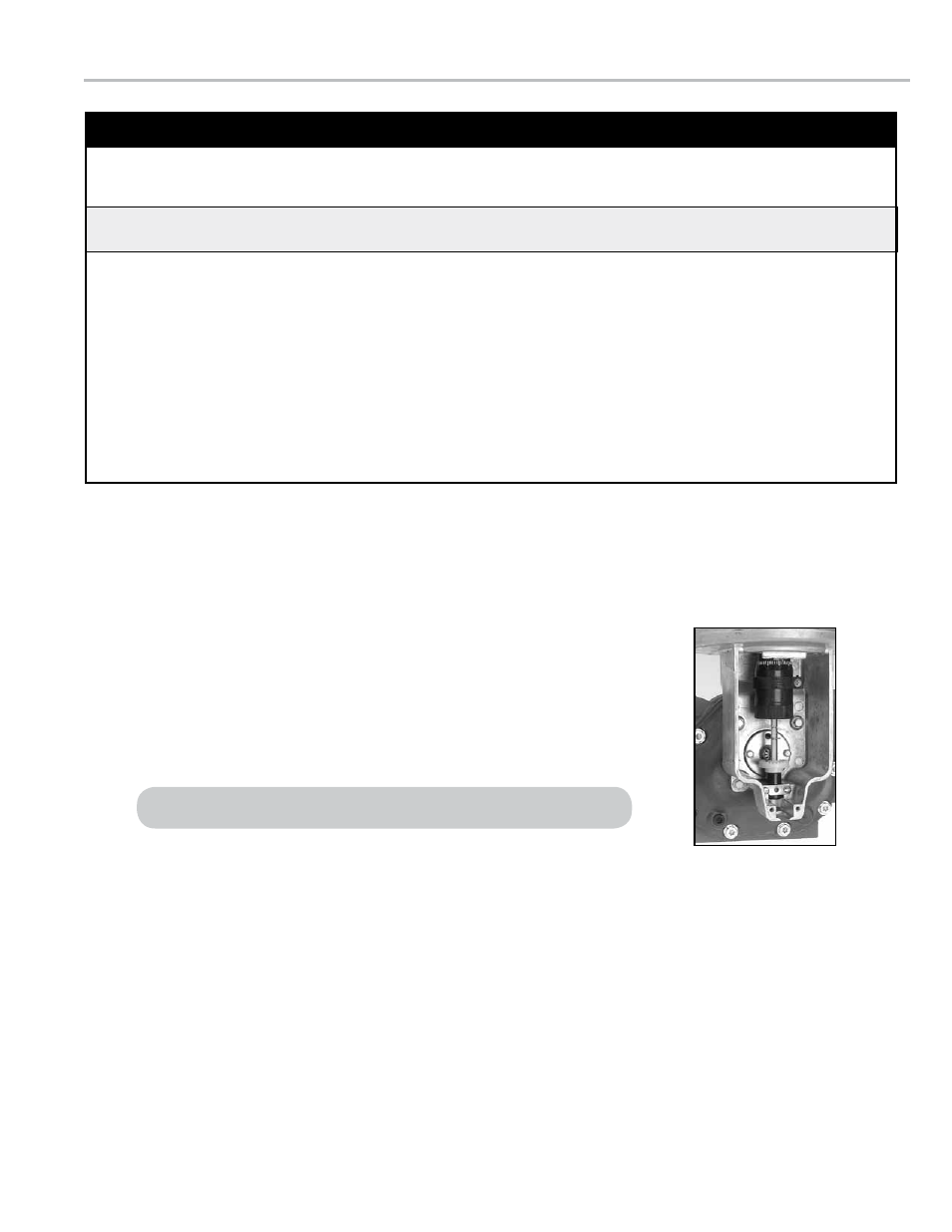
servIcInG the drIve coMponents
removing the dust cover
to remove the dust cover:
1. Cut the dust cover seal wire with side cutters.
2. Remove the dust cover screws with a 5/16’ wrench or slotted screwdriver.
3. Remove the dust cover.
See Relieving Internal Pressure above and the safety procedures on page 3.
relieving Internal pressure
All internal pressure must be relieved to zero pressure before disassembly or inspection of the strainer, vapor eliminator, any
valves in the system, the packing gland, and the front or rear covers.
relieving Internal pressure procedure for lpG and nh
3
Meters
6. Slowly crack the fitting on top of the differential valve to
relieve product pressure in the system. Product will drain
from the meter system.
7. As product is bleeding from the differential valve, slowly
reopen and close the valve/nozzle on the discharge line.
Repeat this step until the product stops draining from the
differential valve and discharge line valve/nozzle.
8. Leave the discharge line valve/nozzle open while working
on the system.
1. Close the belly valve of the supply tank.
2. Close the valve on the vapor return line.
3. Close the manual valve in the supply line on the inlet
side of the meter. If no manual valve exists on the inlet
side, consult the truck manufacturer for procedures to
depressurize the system.
4. Slowly open the valve/nozzle at the end of the supply
line.
5. After product has bled off, close the valve/nozzle at the
end of the supply line.
Serious injury or death from fire or explosion could result in performing maintenance on an
improperly depressurized and evacuated system.
!
WarnInG
13