Installation, Pad mounting (sl585 only) – Controlled Products Systems Group SL58510011G3 User Manual
Page 9
9
I N S T A L L A T I O N
PAD MOUNTING (SL585 ONLY)
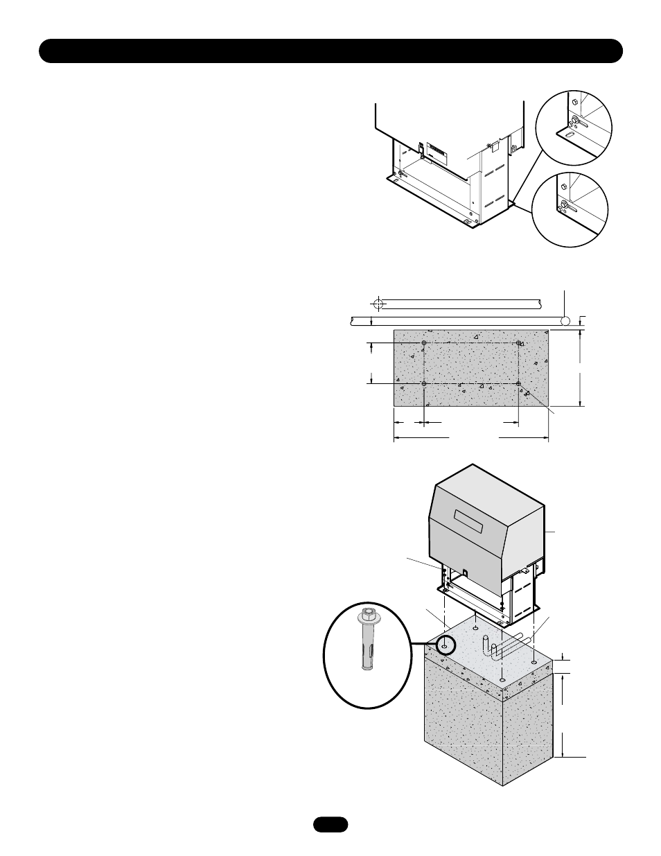
RETRO-FIT INSTALLATION
The operator is shipped from the factory with the lower mounting
angles configured out (Figure 1). If you have pad constrictions,
either angle can be unbolted and reversed to ‘angle in’.
NOTE: If you are replacing an SL580 and wish to use the same
pad mounting hardware, the gate side mounting angle must be
installed angle in.
NEW INSTALLATION
CONCRETE PAD PREPARATION:
1. Lay out concrete pad. (Figure 2).
2. Locate electrical conduit, as required, prior to pouring
concrete.
3. Pour concrete pad.
4. Secure operator (Figure 3) to the concrete pad using four 1/2"
concrete anchors (not provided).
Figure 1
Figure 2
Angle Out
Angle In
Fence Line
Rear of Gate
or Back Frame
1" (2.5 cm)
4" (10.2 cm)
10-7/8"
(27.6 cm)
18" (45.7 cm)
21-1/8" (53.7 cm)
7"
(17.8 cm)
Concrete
Anchor Holes
36" (91.4 cm)
Drive and Idler
Sprocket Toward
Gate Side
Using Suitable Hardware
To Secure Operator To
Concrete Anchors
1/2" Concrete
Anchors
(4 Required)
Power and Control
Wiring Must Be Run
In Separate Conduit
2" to 4"
(5.1 to 10.2 cm)
Above Grade
Depth Required
By Local Codes or
Below Frost Line
Concrete Pad
Figure 3
- SL58510011H3 SL58510021G3 SL58510021H3 SL58510023G3 SL58510043G3 SL58510043H3 SL58510081G3 SL58510081H3 SL58510083G3 SL58515011G3 SL58515021G3 SL5855011G3 SL5855021G3 SL5855023G3 SL5855083G3 SL59510011G3 SL59510011H3 SL59510021G3 SL59510021H3 SL59510023G3 SL59510023H3 SL59510043G3 SL59510043H3 SL59510081G3 SL59510083G3 SL59510083H3 SL59515011G3 SL59515021G3 SL59520043H3 SL59520083H3