Solenoid actuated brake, Friction clutch, Control board programming and features – Controlled Products Systems Group SL58510011G3 User Manual
Page 24
24
To avoid SERIOUS PERSONAL INJURY or DEATH disconnect
electric power BEFORE performing ANY adjustments.
ATTENTION
AVERTISSEMENT
AVERTISSEMENT
AVERTISSEMENT
WARNING
WARNING
CAUTION
WARNING
WARNING
PRECAUCIÓN
ADVERTENCIA
ADVERTENCIA
ADVERTENCIA
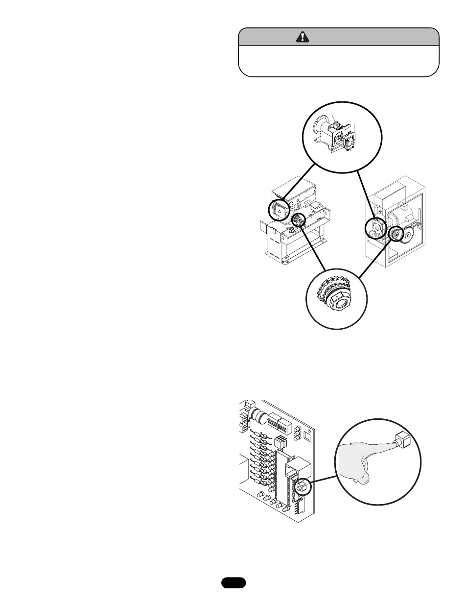
SOLENOID ACTUATED BRAKE
The brake minimizes over-travel caused by gate coasting. An added
feature of the brake is to assist in preventing back driving of the
gate. The brake is spring-applied whenever the motor is not
running. Anytime the motor is running, the electric solenoid
physically releases the brake.
A solenoid brake is standard on SL585/595 operators. The brake is
adjusted at the factory and should not need additional adjustment
for the the life of the friction pad.
Replace friction pads when necessary. Refer to the illustration for
identification of components for the solenoid type brake system.
FRICTION CLUTCH
The friction clutch system is not an automatic reversing device. It
only serves to minimize damage to the gate operator and gate, and
to help minimize vehicle damage. If you need an external automatic
obstruction sensing device, items such as gate edges and photo
beams are available to help protect pedestrians (page 4).
The clutch mechanism must be adjusted properly. During the
installation of the operator, you must tighten the clutch spring lock
nut so it is tight enough to operate the gate, yet loose enough so
that if the gate meets an obstruction, the clutch will slip.
1. Loosen set screws of torque adjustment nut on the gear reducer
output shaft.
2. Back off torque nut until there is very little tension on the
Belleville washers.
3. Tighten torque nut gradually until there is just enough tension to
permit the operator to move the gate smoothly through a
complete open/close cycle, but to allow the clutch to slip if the
gate is obstructed.
4. Re-tighten the set screw that is directly over the flat portion of
the shaft.
CONTROL BOARD PROGRAMMING AND FEATURES
MOTOR LEARN FUNCTION (FORCE PROFILE)
This function is preprogrammed at factory. If either board or motor
is replaced, the control board will need to be reprogrammed to
“LEARN” the specific motor RPM profile of your operator, the red
button “S3” is provided for this. This is important for accurate
force control. Failure to do so may result in improper and unsafe
operation.
NOTE: Motor Learn must be performed in stand alone mode.
1. Ensure that the operator remains attached to the gate
throughout the entire process.
2. Press the motor learn button. The yellow LED should start to
flash rapidly.
3. Push and hold down either the open or the close buttons. The
motor will run for a few seconds and then stop. If the LED goes
out the motor is learned. If the unit activates a limit before
completing the learn or some other error occurs the LED will go
back to on continuously. If this happens try learning while
running in the opposite direction.
Motor
Learn
Button (S3)
Brake Plate
Assembly
Release
Lever
Friction
Pads
Solenoid
Friction Clutch
- SL58510011H3 SL58510021G3 SL58510021H3 SL58510023G3 SL58510043G3 SL58510043H3 SL58510081G3 SL58510081H3 SL58510083G3 SL58515011G3 SL58515021G3 SL5855011G3 SL5855021G3 SL5855023G3 SL5855083G3 SL59510011G3 SL59510011H3 SL59510021G3 SL59510021H3 SL59510023G3 SL59510023H3 SL59510043G3 SL59510043H3 SL59510081G3 SL59510083G3 SL59510083H3 SL59515011G3 SL59515021G3 SL59520043H3 SL59520083H3