Self-regulating heater accessory, Heater wiring diagram for 115v operators – Controlled Products Systems Group SL58510011G3 User Manual
Page 28
28
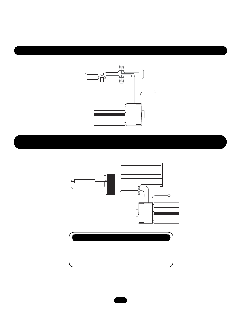
SELF-REGULATING HEATER ACCESSORY
The heater kits are thermostatically controlled heaters that are utilized in areas where the temperature has the potential to drop
below freezing. The heater is adjusted to 15˚C. To change the setting, rotate the temperature control knob on the heater to a new
temperature setting.
NOTE: The temperature readout is in degrees Celsius.
H E A T E R W I R I N G D I A G R A M F O R 1 1 5 V O P E R A T O R S
H E A T E R W I R I N G D I A G R A M F O R 2 0 8 , 2 3 0 , 4 6 0 A N D 5 7 5 V
O P E R A T O R S
HEATER REPLACEMENT PARTS
PART NUMBER
DESCRIPTION
QTY
21-15453-1
Transformer 100VA with 3.2A fuse
1
(208V, 230V and 460V models only)
50-18423
Heater
1
28
White
Black
L1
L2
Green
Ground
)
1
T(
ck
la
B
)
N(
ackl
B
ON
OFF
On/Off
Switch
White
Black
1 PHASE
115 VOLT
POWER IN
Line voltage
to operator
controls
Blue
Grey (575V)
White
(Common)
Black (120V)
)
1
T
ck
(
al
B
)
N
ck
(
al
B
White (Common)
Green
Ground
Violet (480V)
Orange (230V)
Red (208V)
Terminate
unused
transfer
input wires
Yellow
24VAC to
operator
controls
Fusible de 3.2A
Fuse 3.2A
- SL58510011H3 SL58510021G3 SL58510021H3 SL58510023G3 SL58510043G3 SL58510043H3 SL58510081G3 SL58510081H3 SL58510083G3 SL58515011G3 SL58515021G3 SL5855011G3 SL5855021G3 SL5855023G3 SL5855083G3 SL59510011G3 SL59510011H3 SL59510021G3 SL59510021H3 SL59510023G3 SL59510023H3 SL59510043G3 SL59510043H3 SL59510081G3 SL59510083G3 SL59510083H3 SL59515011G3 SL59515021G3 SL59520043H3 SL59520083H3