Controlled Products Systems Group RANGER User Manual
Page 9
7
Ranger actuator support bracket and actuator
bracket are standard and require welding to install
Figure 2A
4”
7”
Direction of gate
movement when opening
Shown in Closed position
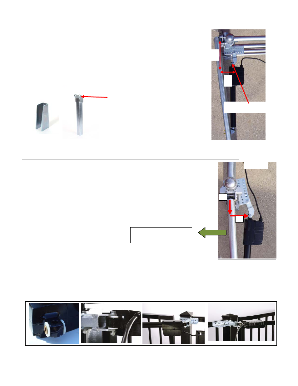
Installing Actuator Support Bracket & Actuator Bracket (Pull To Open)
* B o l t o n b r a c k e t s s h o w n o p t i o n a l
The picture in figure 2 is a Pull to Open installation. When
determining the location of the actuator pivot point all
measurements should be made from the center of the hinge.
The dimensions for a typical 90 degree opening are 5” behind the
hinge center and 7” toward the inside of the property.
Measurements are from hinge center, there are many types of hinges available.
Make measurements from the hinge center.
Installing Actuator Support Bracket & Actuator Bracket (Push To Open)
* B o l t o n b r a c k e t s s h o w n o p t i o n a l
The picture in figure 2A is a Push to Open installation. When determining
the location of the actuator pivot point all measurements should
be made from the center of the hinge.
The dimensions for a typical 90 degree opening are 4” behind the
hinge center and 7” toward the driveway from hinge center. This
type of installation places the bracket out slightly toward the
drive.
Installing Linear Actuator to Actuator Bracket
See figure 3 (Bolt on brackets shown are optional)
1. Install nylon washers and bronze bushings into rear of linear actuator.
2. Install into actuator bracket
3. Secure in place using 3/8 x 2 ½” shoulder bolt and two 3/8 SAE washers.
4. Use 3/8 serrated hex nut to secure, tighten firmly. Do not over tighten.
Important: Actuator should swing freely, Do not over tighten.
Figure 3
Actuator pivot point
5
”
7
”
Actuator pivot point
Gate shown in the full open position
Figure 2