Controlled Products Systems Group RANGER User Manual
Page 8
6
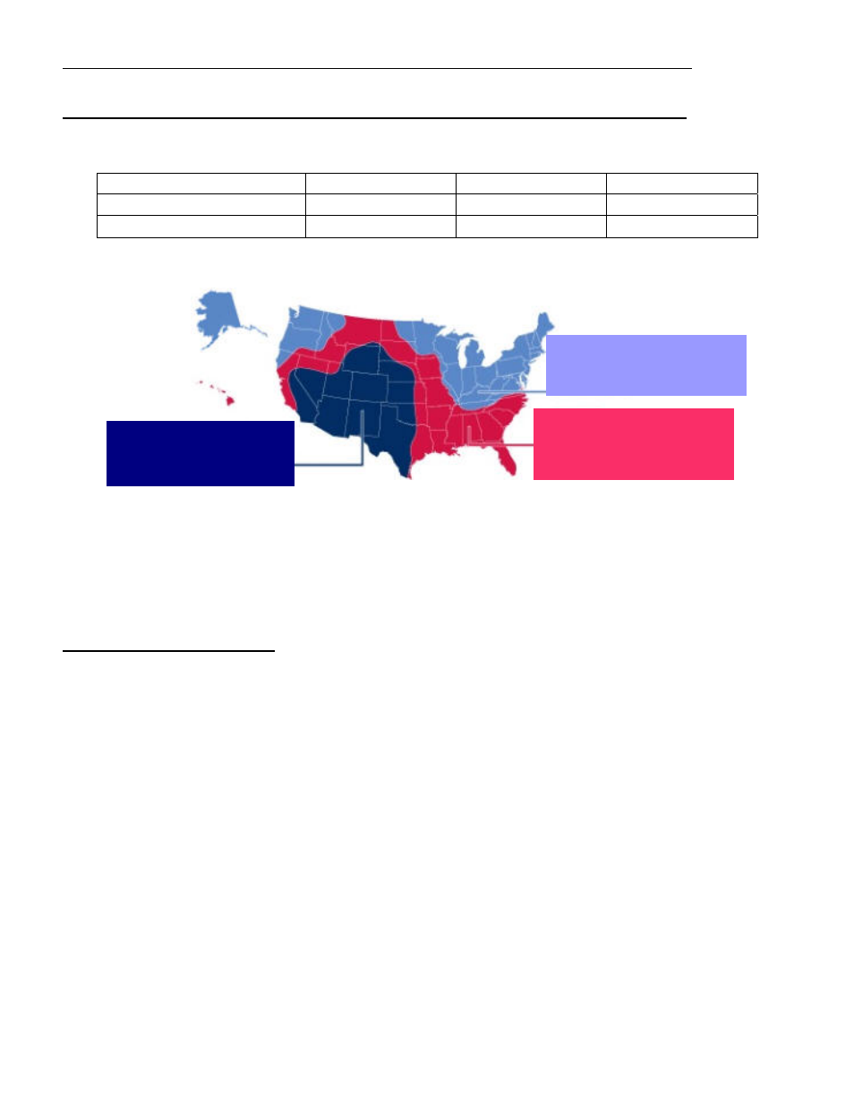
Figure 1
Region 3
Hours of Solar Radiation 5
Region 2
Hours of Solar Radiation 3
Region 1
Hours of Solar Radiation 1.5
GATE CYCLES PER DAY AC CHARGED SYSTEM (TRANSFORMER INCLUDED)
AC charged systems should not exceed 575 cycles per day.
GATE CYCLES PER DAY SOLAR CHARGED SYSTEM (OPTIONAL SOLAR KIT)
Solar charged systems should not exceed the cycles listed in the chart below. These numbers are based on a
single 6 watt solar panel installation. If additional panels are installed additional cycles will be available.
Model Type
REGION 1
REGION 2
REGION 3
Ranger 500 S single gate
10 cycles per day
40 cycles per day
60 cycles per day
Ranger 500 D dual gate
5 cycles per day
20 cycles per day
40 cycles per day
Region 1 covers the area of the country receiving the least amount of solar radiation. On average the amount
of charge time is 1.5 hours in region 1, 3 hours in region 2 and 5 hours in region 3.
These are conservative numbers and the Ranger gate operator should have no problem performing as stated in
the chart above. See Region Map (figure 1) to determine cycles that can be expected. These numbers are
based on a basic system with the standard 6 watt solar panel and adding solar friendly accessories will not
have any great affect on the numbers stated. Using other accessories can cause premature battery failure. Look
for the solar friendly logo when considering accessories for your gate opener.
MOUNTING SITE REVIEW
Review the items below prior to installation and predetermine the solution to any problems which may exist.
A. Does sufficient space exist for mounting and future servicing of the operator and control box?
B. Which direction will the gate swing?
Will the gate operator pull the gate open to the inside (Pull to Open)?
Will the gate operator push the gate open to the outside (Push to Open)?
C. Where will the actuator bracket and gate bracket be secured at the hinge post and to the gate?
D. Where will the control box be mounted to support the weight of the battery and can it be located within
8 feet to prevent splicing of the actuator cable?
E. How far away is the 110 VAC receptacles for the transformer? Transformer is supplied with 12 feet of
cable, if extension is needed use Charge Cable Extension pig tails included. See page 10 for charge
extension information and recommended wire size chart for extension distance needed.
F. Where will the solar panel mount if solar charged so that optimum sunlight is received? Solar panel in
most cases needs to face a south west direction. Solar panel comes with 15’ of cable if extension is
needed use Charge Cable Extension pig tails included. See page 10 for charge extension information
and recommended wire size chart for extension distance needed.
G. How will accessory control wiring, if any, be brought to the control box? Knock outs are provided in
control box bottom for conduit.
H. Have all safety concerns been addressed? (See Safety Section Page 23-24)