L.e.d. display, Possible remedies to fix ‘failures, Charge algorithm – Controlled Products Systems Group RANGER User Manual
Page 14: Maintenance, Solar panel input
12
1. L.E.D. DISPLAY
First 3 seconds upon Charger/Controller powered from Battery or Supplied
Power Supply, the Battery Status Light Emitting Diode (L.E.D.) Flashes.
1.1. L.E.D. Description
EXTERNAL
Illuminates continuously while power from A.C. Power
POWER
Supply Adaptor is sensed.
ADAPTOR
SOLAR
Illuminates continuously while power from Solar Panel
PANEL is
sensed.
DETECTION
If illuminated for longer than 2 seconds check connection
on battery.
CHARGING
Continuous or flashing indicates charging – refer to Charge
Algorithm Section, for further details.
CHARGED
On continuously when AC present and battery fully
charged. Flashes when battery capacity is low.
SYSTEM ERROR If flashing, the charger has entered Failure Mode.
Disconnecting power will reset charger, but if source of
failure is not corrected, Failure Mode will occur again.- refer
to the following Table to Decode the Error Type:
L.E.D.s (First 4 L.E.D.s from Left)
1
st
2
nd
3
rd
4th
Wrong
Battery
Voltage
Off
Off
Off
Flash
Reverse
Battery
Connection
Off
Off
Flash
Off
Thermal
Runaway
Condition Off
Flash
Off
Off
Charge Time Monitor - 1
Off
Flash
Flash
Off
Charge Time Monitor - 2
Off
Flash
Flash
Flash
Excessive
Battery
Drain
Flash
Off
Off
Off
Failed Pre-Qualification Test -1
Flash
Off
Off
Flash
Failed Pre-Qualification Test
-2
Flash
Off
Flash
Off
2. POSSIBLE REMEDIES TO FIX ‘FAILURES’
WRONG BATTERY VOLTAGE
Example: Charger connected to a 24v battery. Reconnect to a battery
rated at 12Vdc.
REVERSE BATTERY CONNECTION
Check and correct any reverse battery.
THERMAL RUNAWAY CONDITION
Old Battery - cells, inside battery, age differently. During charging, and
over the course of many years of operation, OR, many battery
discharges to levels beyond 100% discharged, this error may occur
and the battery(s) may have to be replaced.
CHARGE TIME MONITOR – 1 and 2
Battery pack took too long to complete its charge. Possible causes
include a load (gate cycling repeatedly for a long period of time) during
charging or the battery pack is too large (Many batteries connected in
a parallel circuit). Apply the following formula to determine if the Timer
may run out due to a large battery:
Charge Time = Battery Capacity (AH)
x 1.25
2
Calculated Charge Time must be less than approximately 108hrs.
Output Amps and Battery Capacity (AH - Ampere-hour) are listed on
your battery or contact your battery purchasing source.
Example:
Charge time to for a fully discharged 36 AH battery:
36AH / 2 Amps x 1.25 = 22.5 Hrs - ok to use.
EXCESSIVE BATTERY DRAIN
Excessively high number of cycles discharging the battery beyond
point of no return. Stop gate, and allow battery time to recharge.
PRE-QUALIFICATION TEST - 1 and 2
During Battery testing, if a battery was previously allowed to discharge
to a very low voltage, such as 1 or 2Vdc, the charger puts a low current
through the battery to try to get the battery to come back to life. The
battery may be taking too long to come back.
OTHER POSSIBLE PROBLEMS
No Power on Charger – Check the transformer Supply Adaptor
Plug-in, or the Solar Panel for proper connection.
3. CHARGE ALGORITHM
3.1. PRE-QUALIFICATION TEST STAGE ONE
Charging L.E.D. flashes and applies three battery tests. Further
charging is prohibited if a fault is discovered. If a faulty battery is
suspect, test with a Load Tester (not supplied). Duration of this
stage is dependent on the condition and state of charge of battery
and is approximately 45 seconds to 8hrs.
3.2. CONSTANT CURRENT CHARGE STAGE TWO
Charging L.E.D. illuminates constantly indicating that the charger is
charging the battery at its full rated output.
3.3. CONSTANT VOLTAGE CHARGE STAGE THREE
Charging L.E.D. illuminates constantly indicating that the charger is
charging the battery at a regulated voltage level to top off battery.
3.4. FLOAT CHARGE STAGE FOUR
Charged L.E.D. illuminates constantly. Charger will maintain
battery until AC Power is disconnected and can be left connected
indefinitely.
3.5. RECYCLE CHARGE STAGE FIVE
While left connected to AC Power and Battery, a new charge cycle
is automatically initiated, every 84
th
day.
4. MAINTENANCE
Your new charger requires only a little maintenance. Store in a
clean, dry place and occasionally clean the case and cords (while
the charger is unplugged) with a slightly damp cloth.
10. SOLAR PANEL INPUT
10.1 The Solar Panel produces a lower powered output than the AC
Power Supply Adaptor, which causes the Solar Panel L.E.D. to
illuminate when it is connected.
10.2 The Solar Panel needs to be mounted so that it receives full
sunlight. Even a small amount of shade or blockage will cause the
Solar Panel to Cease charging. Something as tiny as a fingertip
shadow will affect the Solar Panel.
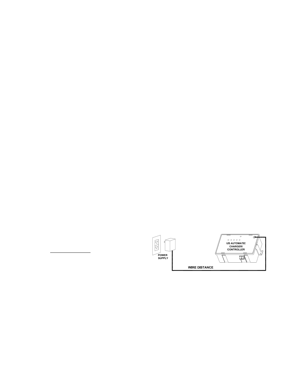
11. RECOMMENDED WIRE GAUGE OVER
LONG DISTANCE BETWEEN CHARGE
DEVICE AND CHARGE CONTROLLER
WIRE DISTANCE AND GAUGE TABLE
See page 16
The wire used must be rated for Direct Burial use, unless in conduit.
Wire ran in conduit must be rated for outdoor use. The above Table lists
the recommended wire gauge per application length. Using a smaller
gauge may impede performance or cause system to malfunction.