Controlled Products Systems Group RANGER User Manual
Page 15
13
Linear Actuator Cable installation
With the control box installed route the linear actuator cable into the bottom of the control box using the 1 ¼”
hole in the rear bottom. Slide the hole plug that is installed on the linear actuator cable into the control box hole
and snap in place (see page 10 figure 14).
If cable length is excessive, coil up and place in the wire compartment of control box (see figure 19).
Ensure the length allows for connection to the Ranger control board Gate 1 connector (see figure 17).
Ranger Quick Connect Harness Final Installation
At this point verify the following items have been completed:
¾ Linear actuator installation is complete.
¾ Control box is securely installed.
¾ Quick connect harness is connected to the charge controller.
¾ Quick connect harness is connected to the battery.
¾ Battery is installed in the battery compartment of control box.
¾ Charge device cable is routed into control box and connected to the charge controller.
¾ Linear actuator cable is routed into control box.
NOTE: Verify above before continuing. If necessary, correct before proceeding.
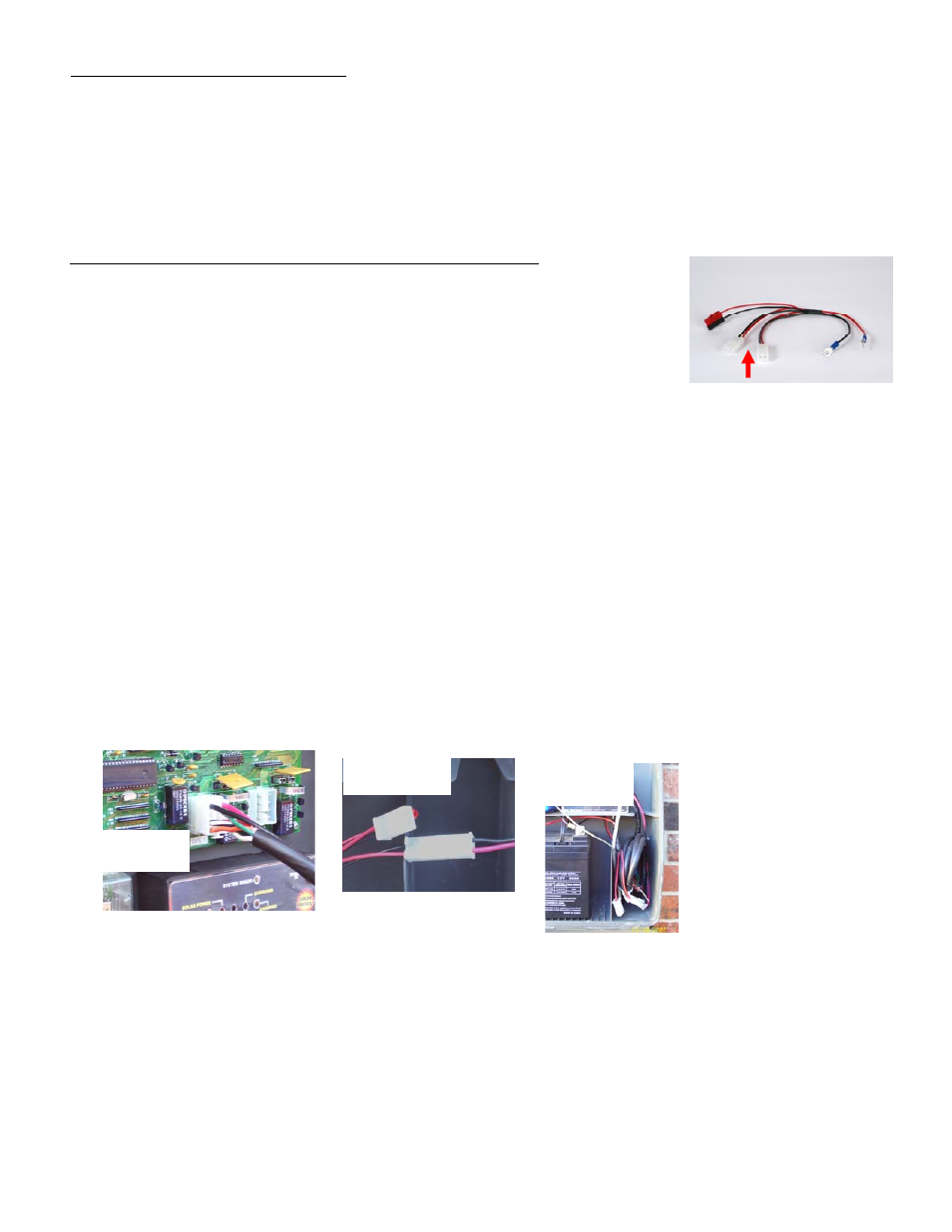
1. Locate the power connector attached to the linear actuator cable (red and black wires).
2. Connect it to one of the Quick connect harness linear actuator power plugs. These connectors are
designed so that incorrect connection is not possible and it does not matter which connector is used (see
figure 18).
3. Locate the linear actuator cable 8 pin plug.
4. Connect it to the Gate 1 connector located on the Ranger Control board (see figure 17).
5. Securely snap in place.
6. Once all connections are made place wires in wire compartment as shown in figure 19.
This completes all cable connections and cable routing into the control box.
NOTE: In case of an emergency at anytime the Gate 1 or Gate 2 connector can be removed from control
board to stop gate from moving.
Figure 16
Gate 1 and Gate 2
Linear actuator power plugs
Figure 18
Figure 19
Figure 17