Controlled Products Systems Group RANGER User Manual
Page 11
9
Figure 8
Mounting Holes
4 Places
Figure 9
Installing Ranger Control Box
The control box should be installed in a location that will not require the eight foot linear actuator cable to be
spliced. If the cable must be spliced refer to splicing instructions below.
Avoid placing the control box behind solid metal objects that might interfere with the receiver reception. The
antenna for the receiver is located inside the control box and this could reduce the operating range.
The control box has 4 mounting holes shown in figure 8, use 4 #12 hex head self tapping metal screws to
securely mount the control box. Verify the structure control box is mounted
on is sufficient to hold the control box and battery securely.
Install control box at this time.
Splicing for Ranger 500 S Linear Actuator Cable (if needed)
The Ranger linear actuator comes with 8 feet of cable. Avoid splicing this cable if
possible. If the control box must be located in such a way that splicing is required
follow the guidelines below to avoid problems.
1. Locate the linear actuator 8 pin connector. Measure 18” from connector and mark.
2. Cut cable at the 18” mark. This will allow enough cable to be spliced and placed in the wire compartment.
3. Bring extension cable into control box and splice 5 wires using wire nuts.
4. Use approved weather tight electrical junction box for the splice located outside the control box.
5. Conduit should be used between junction box and control box. Control box knock out is for ½” conduit.
6. The extension cable must consist of 5 wires, 2 fourteen gauge wires and 3 eighteen gauge wires.
¾ Red wire with white stripe – 14 gauge (distance added is greater than 50 feet use 12 gauge)
¾ Black wire with white stripe – 14 gauge (distance added is greater than 50 feet use 12 gauge)
¾ Orange wire – 18 gauge (distance added is greater than 50 feet use 16 gauge)
¾ Green wire – 18 gauge (distance added is greater than 50 feet use 16 gauge)
¾ White wire – 18 gauge (distance added is greater than 50 feet use 16 gauge)
7. With extension cable now in the junction box strip and prepare to splice to linear actuator cable.
8. Route linear actuator cable into junction box and splice using wire nuts.
NOTE: Cable splice must be water tight to keep moisture away from splices and prevent problems.
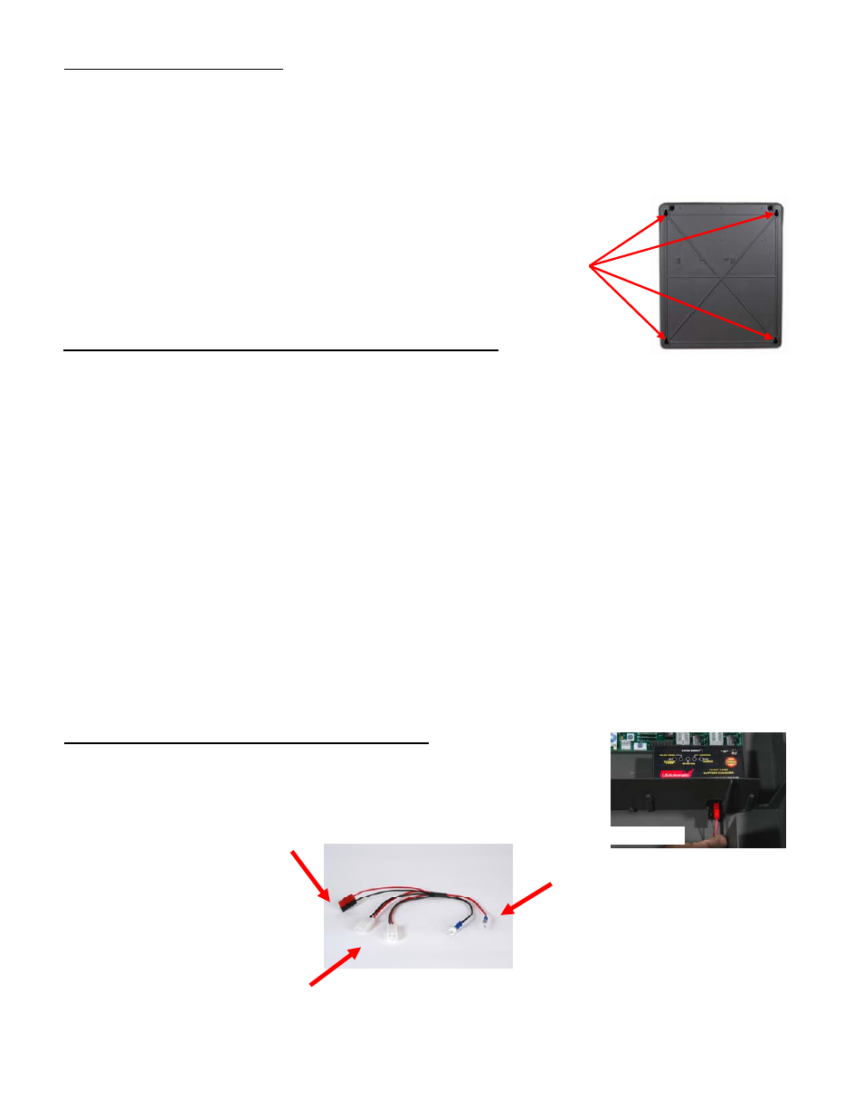
Ranger Quick Connect Harness Initial Installation
Attach the quick connect harness to the charge controller prior to installing
the battery. Plug the charge controller connector into the bottom of the
charge controller (see figure 9). Plug is color coded. Once connected place
harness into wire compartment to prepare for battery installation.
Charge controller connector
R e d c o n n e c t s t o p o s i t i v e b a t t e r y p o s t
B l a c k c o n n e c t s t o n e g a t i v e b a t t e r y p o s t
Gate 1 and Gate 2 linear actuator power plugs
Figure 10
¼”Ring terminal for battery