Controlled Products Systems Group RANGER User Manual
Page 10
8
Figure 5
Figure 6
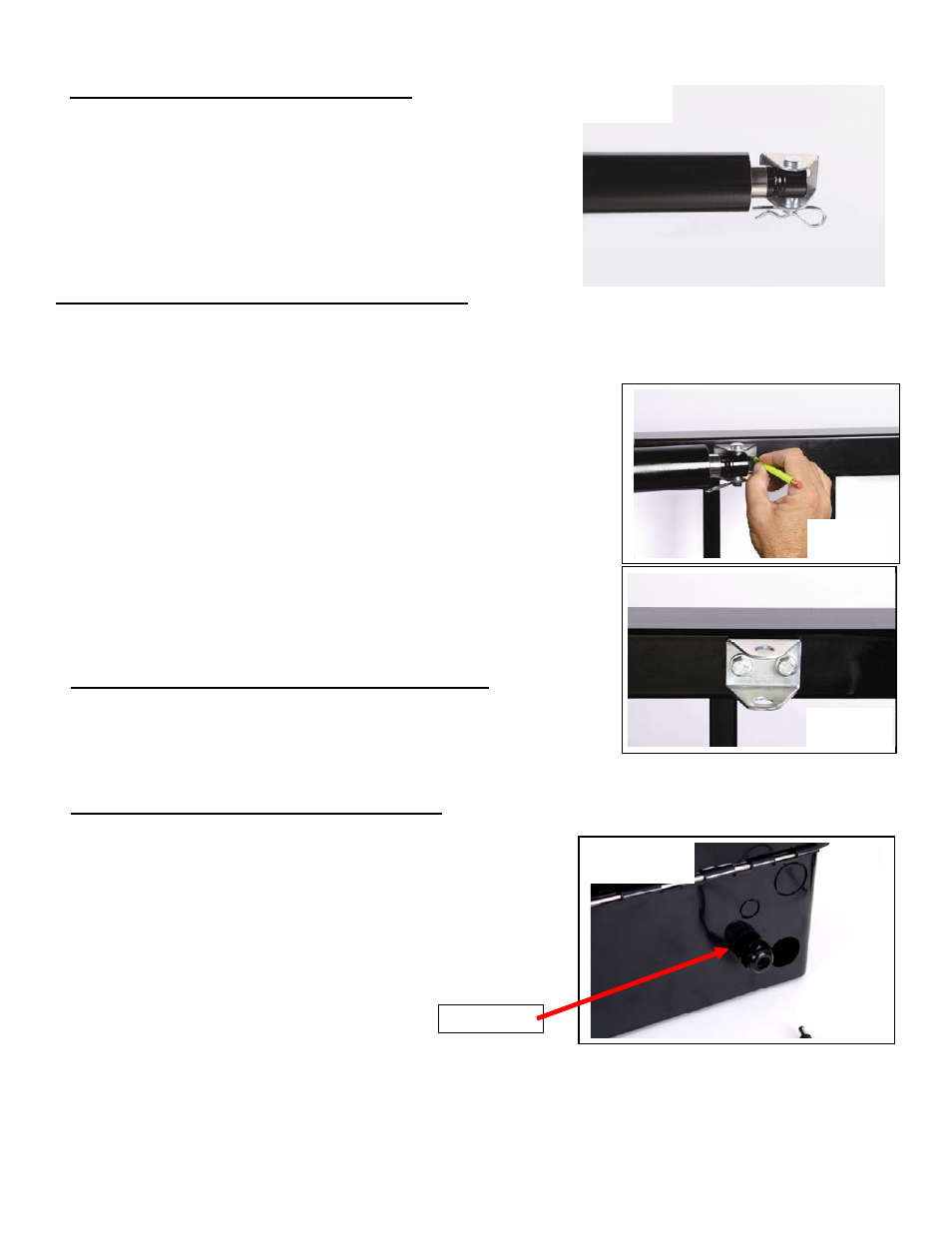
Figure 7
Cable Gland
Installing Gate Bracket to Linear Actuator
See figure 4
Install manual release pin, gate bracket and manual release clip
to linear actuator extension rod end.
Installing Gate Bracket to Gate (Pull to Open Only)
Important: The linear actuator was shipped from the factory set to the fully retracted position. To determine
where the gate bracket will be installed follow the steps below:
The linear actuator should be connected to the actuator bracket at this point.
1. Swing gate to the fully open position.
2. Now open gate another couple of inches (the gate will never open
more than this position). The gate can be adjusted later to open a
little less if needed.
3. Swing linear actuator around (should swing freely) in a level
position to meet the fully open gate. This is where the gate bracket
should be installed on the gate.
4. There are 2 - ¼” holes in the bracket. They can be used to screw the
bracket to the gate before welding if desired (see figure 5 & 6).
5. The gate should now be installed in the fully open position. Verify
that linear actuator is level and all pieces have been installed
correctly.
Installing Gate Bracket to Gate (Push to Open Only)
Procedure is identical to the steps for Pull to Open except the gate will
be in the fully closed position.
Preparing Ranger Control Box for Installation
The control box has two holes in the bottom of the box providing
access to the wire compartment. The large hole is for the actuator
cable and the smaller hole is for the charge device cable.
Install the provided cable gland into the small hole as shown in
figure 7.
Figure 4