Controlled Products Systems Group RANGER User Manual
Page 19
17
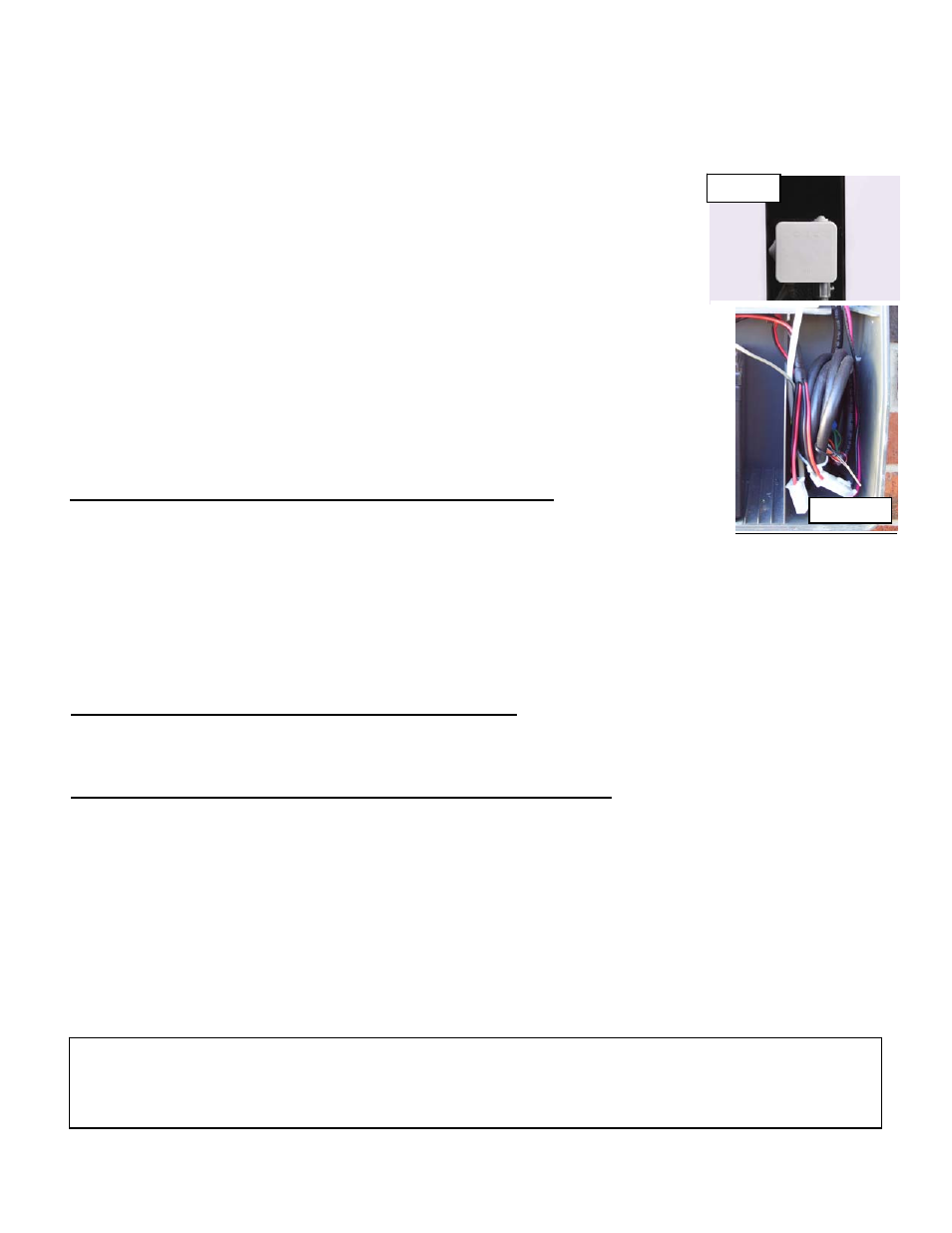
Figure 30
Figure 31
5. If installing conduit attach ½” adapter to junction box. If not, cut rubber knock out (supplied) to fit cable.
6. Install Gate 2 extension cable into the junction box (see figure 28).
7. Using supplied wire nuts connect the 5 wires matching the wire colors (see figure 29).
8. Do not install junction box cover until all connections have been completed
9. With extension cable now installed in junction box, route the other end of the extension cable to the
control box.
10. Install wires into control box wire compartment.
11. Snap 1 ¼” hole plug into control box if conduit was not used.
12. Cut extension cable to length allowing for future considerations.
13. Remove 2” of cable insulation to expose the 5 wires.
Caution: do not damage internal wires.
14. Remove approximately ½” of insulation from each wire.
15. Locate 8 pin connector and pigtail previously cut from Gate 2 linear actuator
cable. Prepare wires for the splice.
16. Connect the 5 wires from extension cable to the 5 wires from the pigtail by
matching the wire colors. Then secure with supplied wire nuts.
17. Roll cable as shown in figure 31 and place in wire compartment.
18. Install junction box cover and securely snap in place as shown in figure 30.
Connecting Gate 2 linear actuator to control board
Locate the power connector attached to the linear actuator cable (red and black
wires).
Connect it to the remaining Quick connect harness linear actuator power plug. These connectors are designed
so that incorrect connection is not possible and it does not matter which connector is used (see page 13 figure
18).
Locate the linear actuator cable 8 pin plug. Connect it to the Gate 2 connector located on the Ranger Control
board (see page 13 figure 17 - Gate 2 connector adjacent to Gate 1). Securely snap in place. Once all
connections are made place wires in wire compartment as shown on page 17 figure 31.
Preparing to Operate Gate 2 for the First Time
Using the “Open/Close Command” button on the control board open Gate 1. This is done because Gate 2 was
just installed in the open position and now both gates should be in the open position.
Operating Gate 2 for the first time and final adjustments
NOTE: See page 15 to adjust close limit utilizing nudge technique.
1. Locate the control switches and turn on switch 4 (press down on the right side).
2. Gate 1 and Gate 2 should be in the open position if installed correctly.
3. Press the “Open/Close Command” button to close Gate 1 and Gate 2.
4. Gate 2 limit adjustment has not been made so it should stop short of fully closed.
5. Turn “OFF” control switch 3, disabling Gate 1.
6. Now use the “Open/Close Command” button to cycle Gate 2 and adjust Gate 2 close limit to match
Gate 1 close position.
7. With both gates now closed, turn “ON” control switch 3 enabling Gate 1.
8. Press “Open/Close Command” to open both gates and then close, adjust limit positions if necessary.
CAUTION:
T o r e d u c e t h e r i s k o f i n j u r y , U S A u t o m a t i c s t r o n g l y r e c o m m e n d s t h e i n s t a l l a t i o n o f a d d i t i o n a l
s a f e t y d e v i c e s s u c h a s P h o t o E y e S e n s o r s a n d S a f e t y E d g e s . C o n s u l t a n a u t h o r i z e d i n s t a l l i n g d e a l e r
o r s e e t h e S a f e t y S e c t i o n o f t h i s m a n u a l o n p a g e s 2 3 & 2 4 .