Protection device schematic – Controlled Products Systems Group HTG 320-2 ST User Manual
Page 40
StrongArm Installation and Reference
30
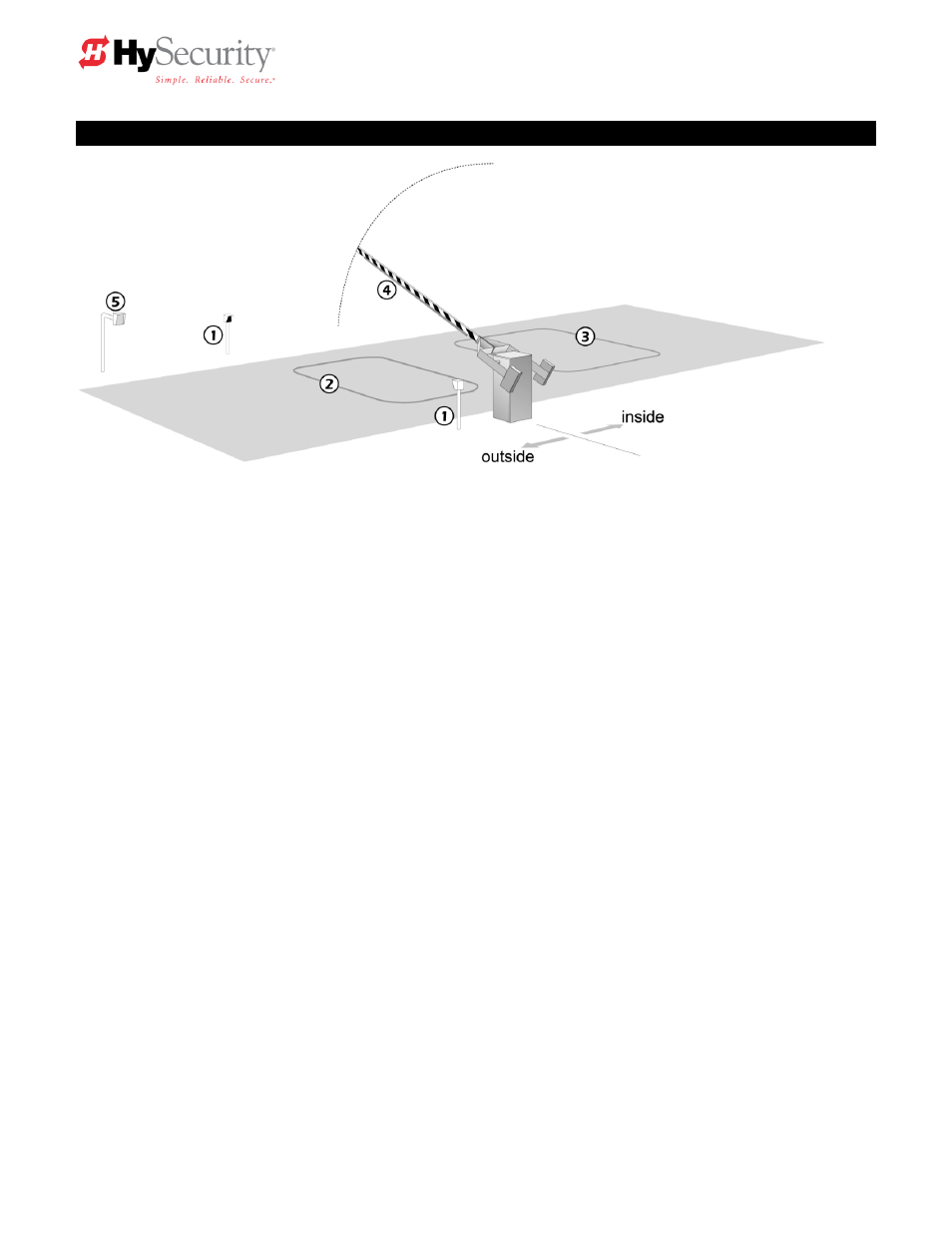
Protection Device Schematic
System Elements
1. Photo Eye
2. Reset Loop / Obstruction Loop Vehicle Sensor
3. Free Exit Loop Vehicle Sensor
4. Gate Edge Sensor
5. Entry Device
6. Optional Audible Buzzer
Although many optional vehicle loop sensor configurations are possible, the schematic above is provided
to represent a typical system layout for a barrier arm gate. Automatic vehicular gates are for automotive
use only. Be certain to design the installation such that all pedestrian traffic is directed to a separate
walkway. Install signs that warn of the hazard of a moving vehicular gate.
Do not locate the barrier arm gate such that it moves within two feet of a rigid object. Even though there
is an exclusion in the UL325 standard that states: ―any vehicular barrier arm that is not intended to move
toward a rigid object closer than 2 feet does not require protection for entrapment
.‖ HySecurity
recommends that the designer and installer employ the use of a gate edge and a photo eye in the event
that a pedestrian strays into the area.