Installation – Controlled Products Systems Group HTG 320-2 ST User Manual
Page 20
StrongArm Installation and Reference
10
Installation
4. Electrical power Connection
This operator is intended for permanent
installation, so all electrical conduits must be
properly connected to the control box. The
entry for the primary power is a ½ -
¾‖ knockout
on the left side of our control box next to the on-
off switch. This operator was built to run on a
specific voltage and phase for line power. Make
sure the available line voltage and phase
matches the nameplate on this machine. Also
be certain that the wire size of the branch circuit
vs. the distance of the run from the main panel
is large enough to avoid excess voltage drop. At
a minimum, a 20 amp circuit (protected with a
20 Amp Inverse Time Breaker) should be
provided. Also be sure the operator is
electrically well grounded per NEC Article 250
and local codes. See the Appendix section for correct wire sizes and detailed electrical wiring
information.
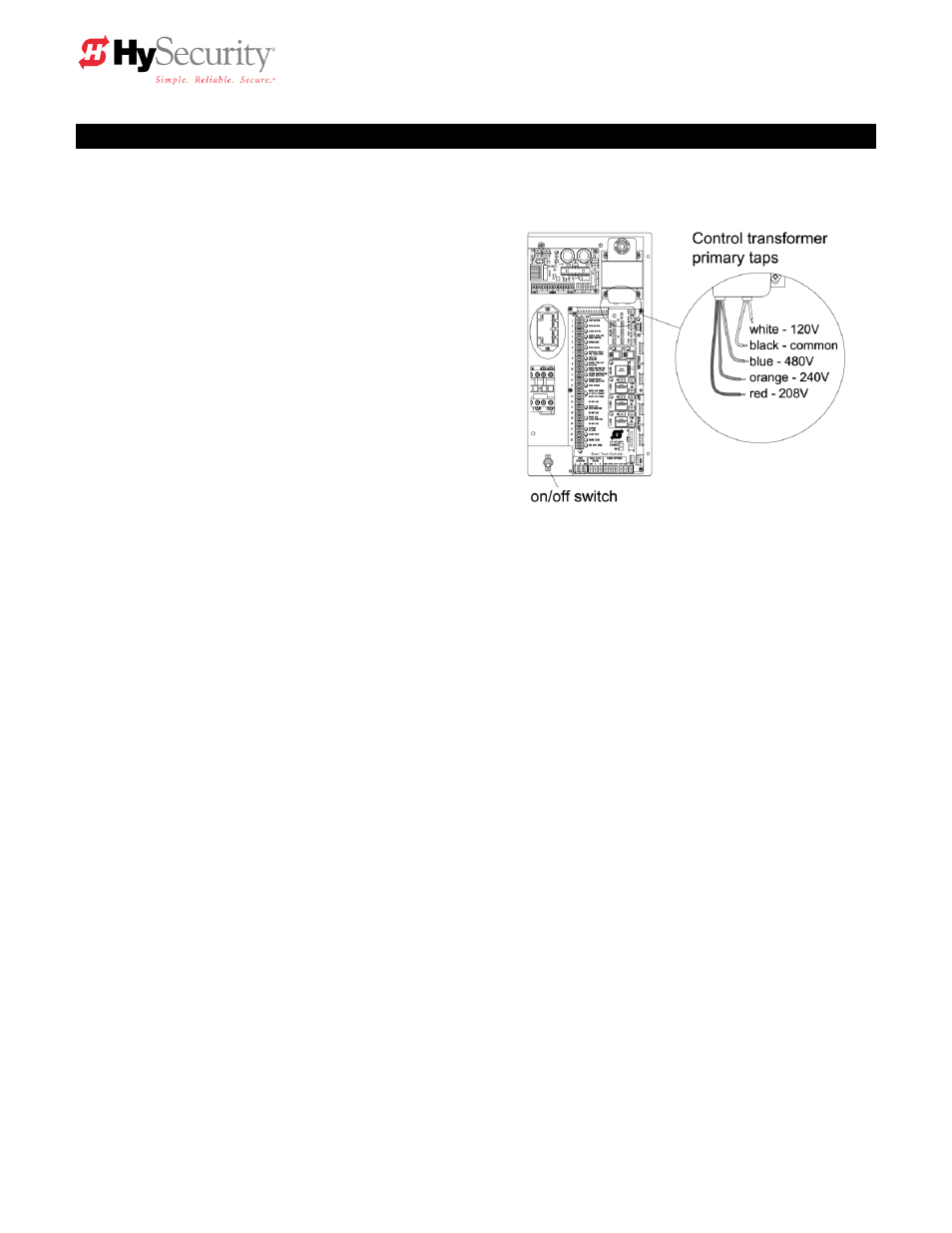
5. Primary tap of Control Transformer (not on DC battery powered operators)
Check to make sure that the primary tap on the control transformer matches the line voltage you
have connected to the operator. Measure the line voltage carefully to distinguish between 208V
and 230V branch circuits. A label on top of the transformer identifies the various taps.
6. Power Connection for Two Part Battery Operators
The primary AC power must be routed to the DC power supply enclosure, but there must
conduits between the gate operator and the DC supply enclosure. Note: AC power is not needed
in the gate operator enclosure, unless there is an optional heater. Three separate DC circuits are
required between the battery supply and the gate operator. Heavy gage wires to supply the
motor and two 14-gage circuits for the controls. The heavy gauge wire must be at least 6-gauge
if the DC supply is within 20 feet of the operator, but must be increased to 2-gauge if the DC
supply is located farther from the operator. For full details, review the section titled ―Two Part
Operators‖.
7. Replace the Vent Plug!
Remove the
½‖ steel or plastic shipping plug on the pump manifold (left rear corner) and replace it
with the supplied black breather cap.
8. Configuring the Smart Touch Controller
The operator controls will not allow the gate to function until the Smart Touch Controller has been
configured. Wait to connect the external controls until you have reviewed the Smart Touch
Controller instructions, and tested the basic functions of the operator. Review the Smart Touch
Setup section.