Installation preparation checklist, Installation – Controlled Products Systems Group HTG 320-2 ST User Manual
Page 19
StrongArm Installation and Reference
9
Installation Preparation Checklist
1. Read all of the instructions, especially the
Important Information in Section 1 at the
beginning of this manual, before you attempt
installation. This section is focused upon
mechanical installation. For electrical setup,
refer to Section 3, on system configuration
and use of the Smart Touch Controller.
2. Pour a concrete mounting slab that is a
minimum of 2
0‖ x 20‖ x 20‖ with the electrical
conduits located correctly to enter the
chassis. Keep in mind that a space of 7 X 11‖
just inside of the operator door is where the
conduits must enter into the operator.
HySecurity recommends a slab reaches
below the local frost line. See the footprint
plan and elevation view on pages 13-15.
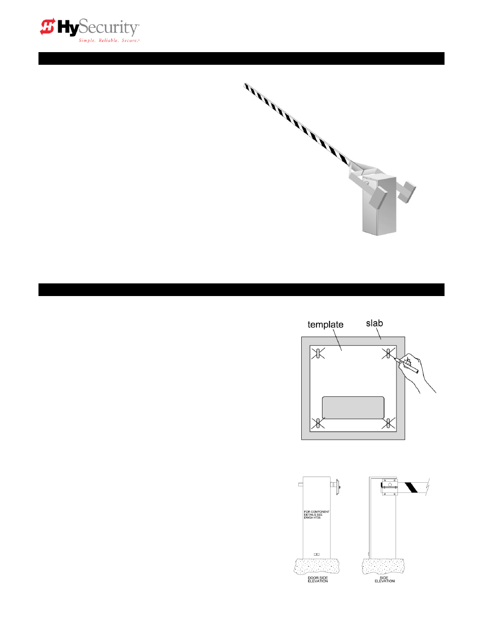
Installation
1. Drill four holes for concrete anchors
The operator must be mounted with four anchor bolts.
The
se will be 12.5‖ on center with a square pattern to
match the chassis base. Line up the operator so that the
end of the barrier arm is in the intended position. Place
the operator over the conduit and mark the mounting
holes. Once marked, remove the operator and drill for
½‖ min. anchor bolts.
2. Line up the operator
Set the operator over the mounting bolts, align the
operator and securely tighten the bolts.
3.
Special two part operators
DC powered operators come with a separate power
enclosure. This enclosure should be mounted
within 20 feet of the operator. We recommend wall
mounting or using two 4‖ posts, with horizontal
mounting strut to create a support for this
enclosure. See also step 6 and section 8 on two
part operators.