Smart touch controller inputs – Controlled Products Systems Group HTG 320-2 ST User Manual
Page 30
StrongArm Installation and Reference
20
Wiring Control Inputs to the Smart Touch Controller
1. Test open and close before wiring the external control inputs. This makes it easier to troubleshoot
if an unexpected functionality
arises. ―New Generation‖ Smart Touch Operator inputs (after Sept.
2006) use an LED to indicate when it is active. DC operators operating without AC require you to
push and hold an LED button to disclose input status. This button is in bottom corner near the
Fire Department Open input. [
“Classic,‖ pre-Sept. 2006 operators LEDs are only lit when you
push the Tact button. The Tact button is located on the top left corner, near the Stop Button input
on the Classic Board.]
2. All the control device inputs listed below are shown as a single input. The 2nd wire is connected
to the Common Terminal Buss on the Power Supply board. The Emergency Close and Fire Dept.
Open inputs are an exception and require a +24 Volt input. The +24 is located on the spade
terminals next to the Common Buss. See pictures on the next page.
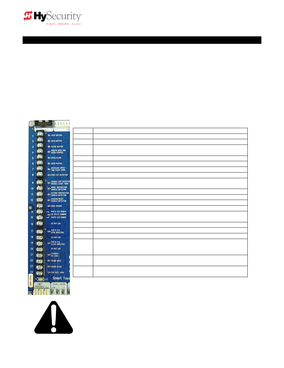
Smart Touch Controller Inputs
1.
*Stop Push button N.C. input, jumper to Common if unused
2.
*Open Push Button Not for radio or remote access controls
3.
*Close Push button Not for radio or remote access controls
4.
Remote Open & Radio Control For radio / remote open device
–
Program to also Close using Smart Touch menu
5.
Open/Close button Pushbutton or radio controls
6.
Partial Open (This input disabled on barrier arm gates)
7.
Open interlock input or Time clock Open Menu configurable
8.
Free Exit vehicle detector
9.
Disable Free Exit vehicle detector or Timer to Close
Free Exit is only disabled when Close Limit Switch tripped
10.
Inside Obstruction vehicle detector Inside reversing loop
11.
Outside Obstruction vehicle detector Outside reversing loop
12.
Reset vehicle detector (Closing loop under arm)
13.
Edge Sensor One input works for both travel directions
14-15.
Photo eye Common Power
Supply for PE power & PE Com
17.
Photo eye Open direction
19.
Photo eye Close direction
21.
Charger AC power loss Only used in DC, battery type operators
22.
Spare Input Software
≤ h3.26,- non functional,
Gate Lock Interlock Input Software > h3.26, prevents start until
external gate lock releases
23.
**Emergency Close Must menu enable and input +24 Volts to trigger.
Overrides photo eyes, gate edge & vehicle detectors.
24.
**Fire Dept. Open Must menu enable and input +24 Volts to trigger.
Overrides photo eyes & gate edge.
*
Do not connect an external control to terminals #1, 2 or 3, unless controls are
located in clear view of the entire gate area. Out of sight controls: use input
terminals #4, 5, 6 or 7.
**
The Emergency Close and Fire Dept. Open inputs are to be used only if
access to these controls is guarded such that there is always supervision
when activated.