Controlled Products Systems Group 6500-083 User Manual
Page 31
30
6500-065-E-2-08
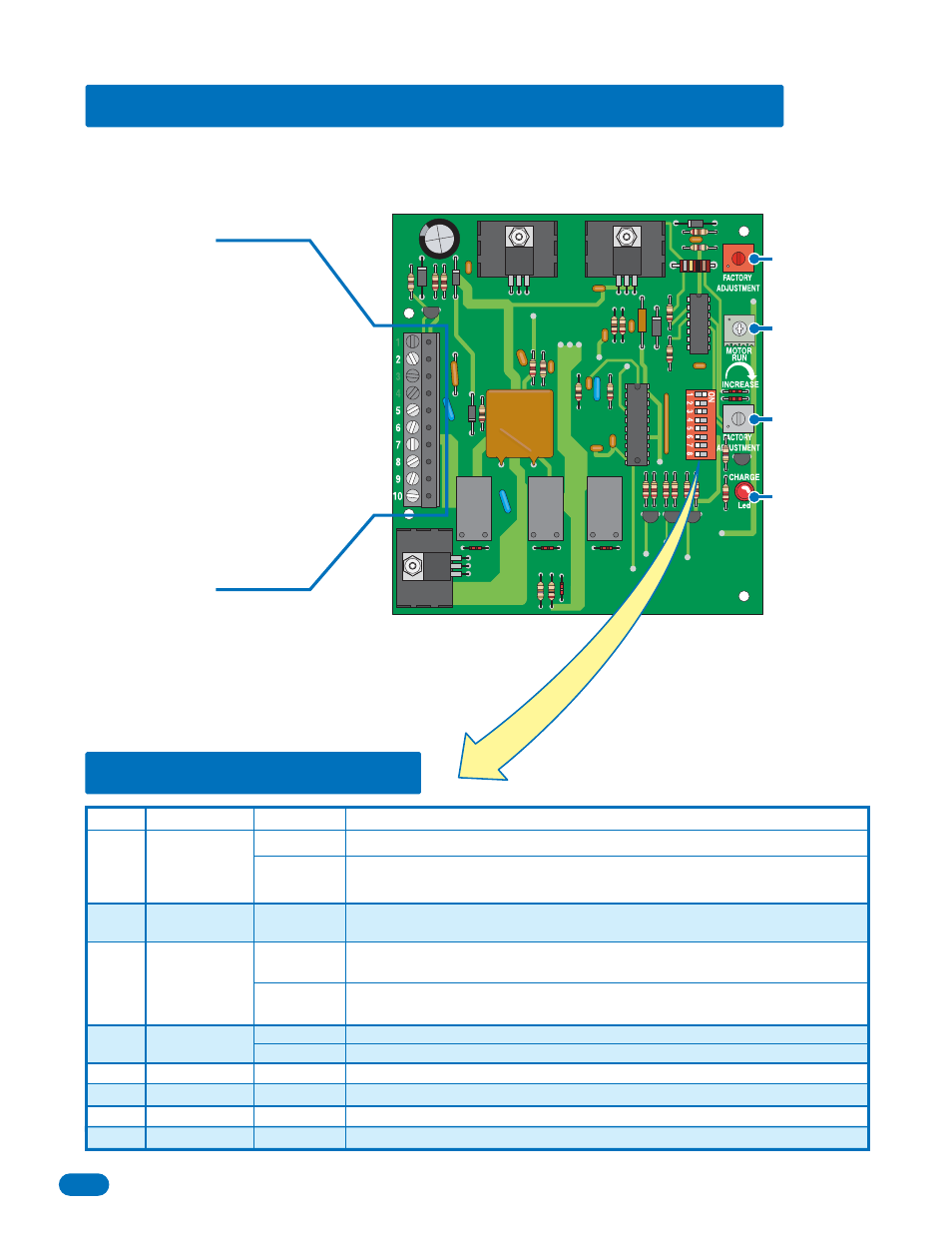
1. COMMON not used.
2. OPEN
INPUT
3. RADIO POWER 24 -Volt power not used.
4. ACTIVATION OUTPUT not used.
5. 24
VAC
INPUT
6. 24
VAC
COMMON
7. BATTERY POSITIVE INPUT
8. BATTERY NEGATIVE INPUT
9. DC MOTOR POSITIVE OUTPUT
10. DC MOTOR NEGATIVE OUTPUT
5.3 DIP-Switch Settings
5.2 Terminal and Board Adjustment Descriptions
Switch
Function
Setting
Description
Operation
Changes
Open Direction
Automatic
Power-up
Activation
OFF
ON
OFF
ON
Operator
Type
Not Used
Not Used
Do Not Adjust
Do Not Adjust
Timer Not Used
Charging LED
Not Used
Not Used
1
2
3
4
5
6
7
8
Gate will automatically open when a power outage occurs. Switch must be in the
ON position.
Set so that the gate runs to the open (up) direction upon loss of AC power.
OFF
ON
OFF
ON
When AC power is restored, an input (push button, loop, radio receiver, etc.) is
required to return the gate to normal operation.
When AC power is restored, a 1-second pulse is sent to the gate operator input to
automatically restore normal operation.
Must be in the ON position.
2340