6 determining arm lengths 1.5 attach gate bracket, Caution – Controlled Products Systems Group 6500-083 User Manual
Page 13
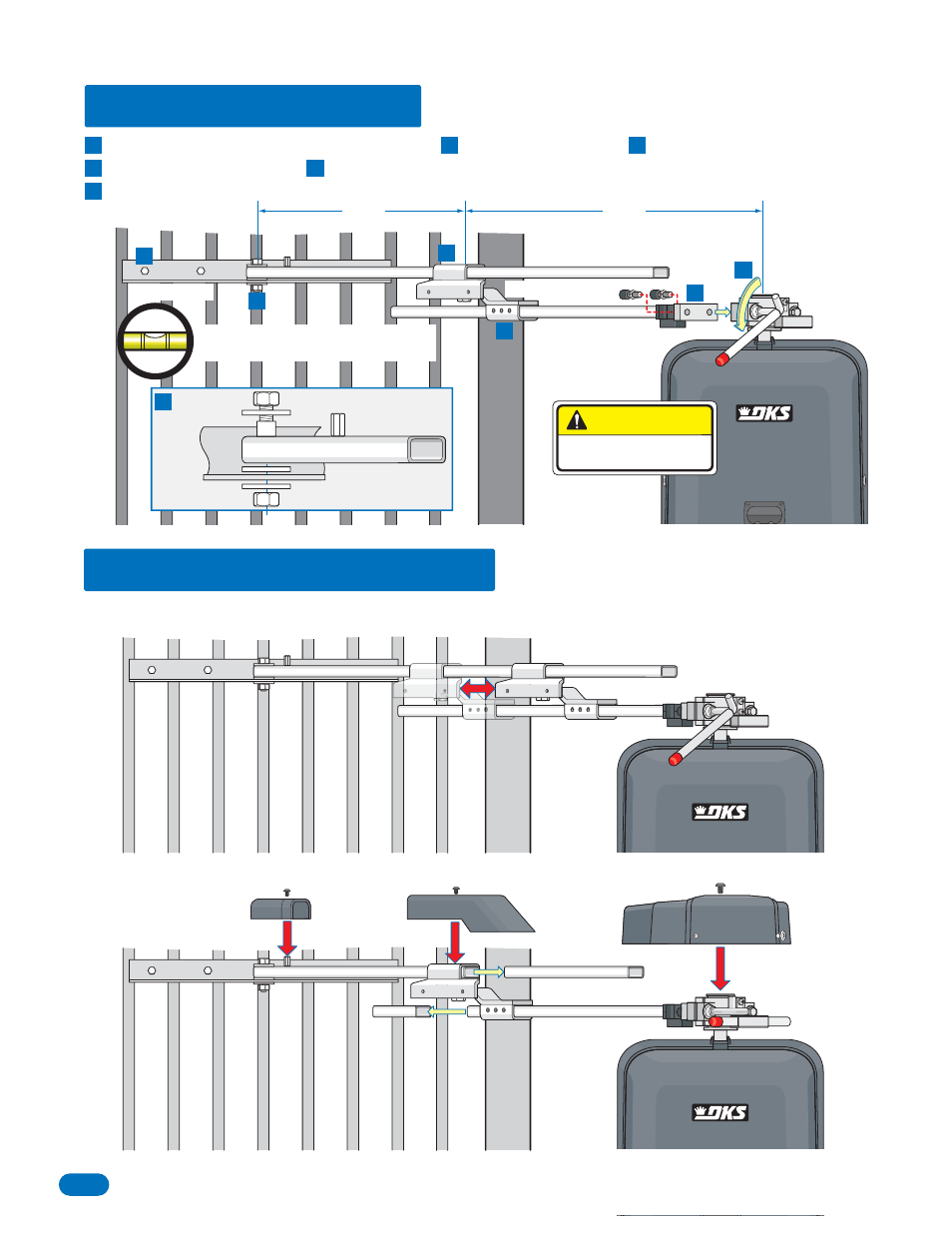
Gate Bracket
Crank Arm
Control Arm
Arm assembly and gate bracket MUST
be level for correct bracket location.
Release hub with release tool.
DO NOT REMOVE HUB!
Bolt crank arm to operator. Slide elbow assembly on crank arm.
Bolt control arm to gate bracket. Slide control arm into elbow assembly. KEEP ARM ASSEMBLY LEVEL.
Bolt gate bracket to gate.
1.6 Determining Arm Lengths
1.5 Attach Gate Bracket
Slide elbow assembly back and fourth, manually opening and closing gate until satisfied with the gate’s 90° open and fully
closed positions.
Mark and cut off excess arms. Secure arms to elbow assembly with 6 allen screws. Tighten hub and replace release tool. Install
safety covers.
excess
excess
Elbow Assembly
Typical Arm
Pivot Point
Lengths
26
1
/
2
”
26
1
/
2
”
CAUTION
DO NOT REMOVE HUB!
A
A
D
F
F
E
E
D
B
C
C
B
Gate
Bracket
Control Arm
D
12
6500-065-E-2-08