6 auxiliary device wiring – Controlled Products Systems Group 6500-083 User Manual
Page 19
18
6500-065-E-2-08
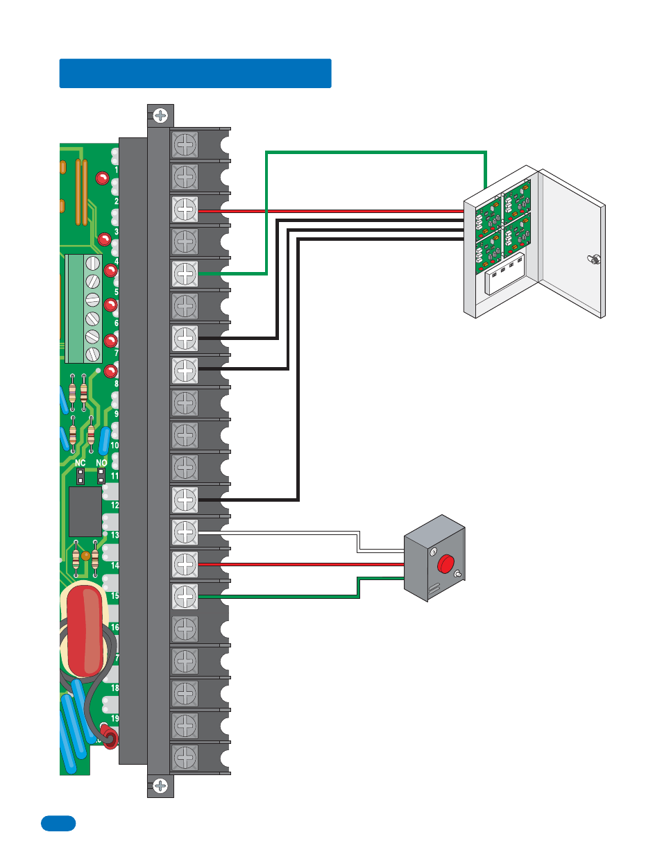
2.6 Auxiliary Device Wiring
20
19
18
17
16
15
14
13
12
11
10
9
8
7
6
5
4
3
2
1
The Remote Alarm Reset Station (Model
1404-080) MUST be mounted in the
line-of-sight of the gate operator.
Terminal 5 required only if the tracker board
will activate the gate operator. Refer to the
manual 2351-065 for detailed information.
Using a 2351-010 Tracker
Expansion Board, operator data
can be sent to the access
controller. Models 1833, 1835,
1837 or 1838 only. Refer to the
manual 2351-065 for detailed
information.