Controlled Products Systems Group 107725 User Manual
Page 9
Page 9
June, 2004
750 Operator And
455 D Control Panel Installation Manual
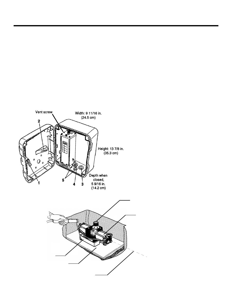
Figure 5. Parts of the Power Unit in the vinyl box
Caution: NEVER weld the base plate of the drive unit
to the foundation plate. Weld only the mounting C
brackets to the foundation plate.
When the position of the drive unit meets these
conditions, weld the C-shaped mounting brackets to the
foundation plate to hold the drive unit in position (see
Figure 6).
Next you need to prepare the two L-shaped "box halves"
for installation. Note that the lip on each piece should
be on top so as to support the top cover. Make the
necessary holes for the two hydraulic lines that run
from the drive unit to the power unit.
Once you have made your access holes, you can weld
the box halves to the foundation plate and to one
another so as to enclose the drive unit on four sides. Be
sure to protect the drive unit during welding.
I
NSTALL
THE
D
RIVE
U
NIT
To install the drive unit, first make sure the four
leveling bolts on the base of the unit do not protrude
from the bottom of the unit. Then place the unit on the
foundation plate (see Figure 6).
Position the drive unit according to the following:
The side of the drive unit with the splined shaft should
be the side nearest the gate post.
The longitudinal axis of the drive unit is perpendicular
to (at right angles to) the fully closed gate leaf.
The center of the splined shaft is vertically aligned with
the center of the gate hinge axis (use a plumb line).
6
1 Lock for triangular key
2 Clip to hold instruction manual
3 1 1/16 in. (3 cm) holes for hydraulic lines
4 1 1/16. in (3 cm) knock-outs
5 Three knock-outs, each measuring
3/4 in. (2 cm)
Splined shaft: This side
of the drive unit should be
nearest the gate post.
Drive unit
Foundation
plate
Mounting
C bracket
Longitudinal axis
of the drive unit
Figure 6. Welding the mounting C-bracket
to the foundation plate