Npacking, Perator – Controlled Products Systems Group 107725 User Manual
Page 5
Page 5
June, 2004
750 Operator And
455 D Control Panel Installation Manual
U
NPACKING
THE
O
PERATOR
When you receive your 750 Operator, complete the
following steps:
Inspect the shipping box for physical damage such as
leaking oil or a torn carton. Then inspect the operator
after you remove it from the box. Notify the carrier
immediately if you note any damage because the carrier
must witness the damage before you can file a claim.
As you unpack the boxes, insure that all parts listed
below are included:
Power Unit (see figure 1a):
(1) vinyl box with key (the power unit is shipped
separately from the box)
Drive Unit (see figure 1b):
(1) Hydraulic drive attached to its base plate with four
(4) leveling bolts installed and with the sleeve fitted
over the splined shaft.
(2) “Box halves” (right-angled and lipped pieces of
galvanized steel that together form the sides of the
box around the drive unit)
(1) Top cover protected by peel-off plastic
(1) Package containing two (2) mounting C-brackets, six
(6) screws to hold cover on the drive unit, four (4)
ring fittings for hydraulic lines, one (1) plastic half-
sleeve to fit around drive shaft and match top cover,
one 0.3-qt (1/4 liter) container of hydraulic fluid
(1) Plastic collar around splined shaft
(a)
(b)
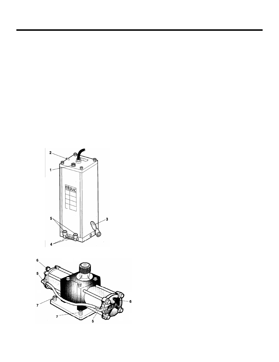
1 Oil Plug/Dip Stick
2 Vent
Screw
3 Manual Release Lever
4 By-Pass Valve Screw
5 Hydraulic 90-deg Elbow Couplings
6 Bleed
Screws
7 Leveling
Bolts
Figure 1. Parts of the 750(a) the Power Unit and (b) the Drive Unit
(sometimes referred as to the Ram Unit)