Controlled Products Systems Group 107725 User Manual
Page 13
A
B
C
D
E
F
Page 13
June, 2004
750 Operator And
455 D Control Panel Installation Manual
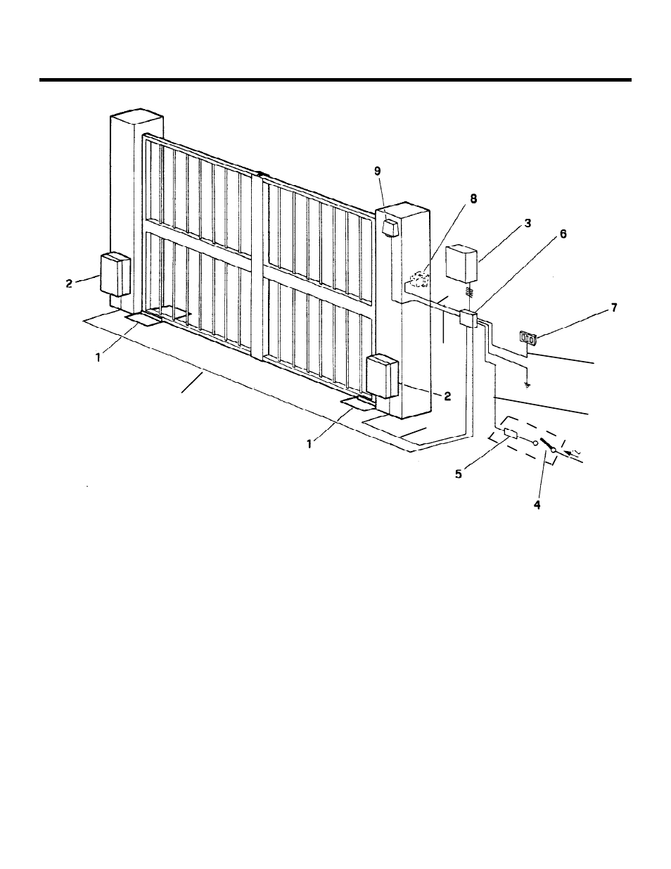
Figure 11. Typical layout of gate system with 750 Operators
Gate System Parts
Wire Gauges for Given
Power Source Voltage
220 VAC
115 VAC
1
750 hydraulic drive unit
A
4 X 14 AWG
4 X 14 AWG
2
750 hydraulic power unit
B
4 X 14 AWG
4 X 14 AWG
3
750 Control Panel box
C
3 X 18 AWG
3 X 18 AWG
4
Main power switch
D
5 X 18 AWG
5 X 18 AWG
5
Circuit breaker
E
5 X 18 AWG
5 X 18 AWG
6
Main junction box
F
4 X 14 AWG up
3 X 14 AWG up
7
Switch for 750 Operator
to 414 ft (126 m)
to 130 ft (40 m)
8
Switch for 750 Operator
or 3 X 10 AWG up
9
Radio receiver
to 340 ft (104 m)
Locate Activation Devices at
least 10 ft from the gate