Controlled Products Systems Group 107725 User Manual
Page 11
Page 11
June, 2004
750 Operator And
455 D Control Panel Installation Manual
a minimum of 5 3/4 in. (2.1 cm) long and must be as
wide as the gate leaf is thick and must fit as tightly as
possible to minimize leaf movement within the shoe
(see Figure 9).
Construct the U-shaped section of the shoe and verify
that it fits around the gate leaf. Position the U-shaped
section over the splined shaft so that the leaf's axis of
rotation will fall within the minimum dimensions shown
in Figure 10.
On the U-shaped section of the shoe, mark the position
for the leaf's axis of rotation. Next, drill a pilot hole in
the U-shaped section to mark the axis of rotation point
and mark the position for the placement of the vertical
section of the shoe.
Next you need to position the sleeve for the splined
shaft of the pinion (or the shear-pin assembly) on the
bottom side of the U-shaped section of the shoe as
shown in Figure 9. On the bottom of the U-shaped
shoe section, center the sleeve around the pilot hole
that marks the axis or rotation. Accurately centering
the pilot hole is important.
Caution: NEVER weld the splined shaft to
anything.
Spot-weld the sleeve into place on the bottom of the
shoe's U-shaped section. If you are using the shear-pin
assembly, spot weld the sleeve to the bottom of the
shear-pin assembly, and spot weld the top of the
shear-pin assembly to the bottom of the shoe’s U-
shaped section.
Next you must test the temporarily welded position of
the splined shaft's sleeve. Fit the shaft sleeve over the
splined shaft with the U-shaped section aligned in the
gate leaf's fully closed position. Verify with a plumb
line that the axis of rotation falls through the pilot
hole to the center of the splined shaft.
If the axis of rotation alignments are correct, then
permanently weld the sleeve for the splined shaft to
the bottom of the U-shaped section of the shoe.
Also, you now need to weld the pilot hole closed, and
you need to weld the vertical section of the shoe to
the U-shaped section of the shoe.
Lubricate the splined shaft with grease and place the
finished gate leaf shoe over the shaft in the closed
position.
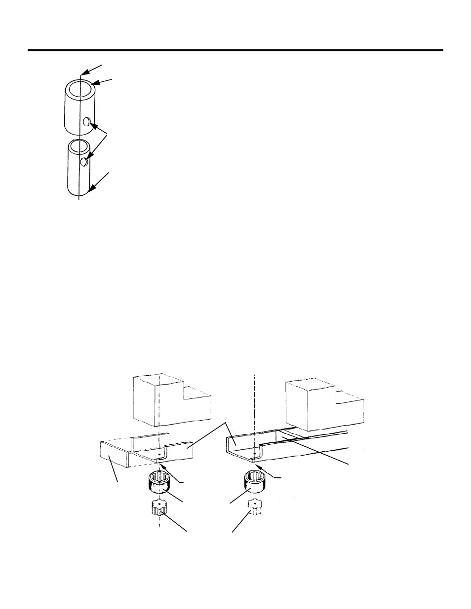
Weld this end of this pipe to
the bottom of the gate leaf
shoe, being certain you have
aligned the axes of rotation.
This 2 in. pipe (schedule 160)
has an inside diameter of 1.689 in.
Weld this end of this pipe to the
sleeve
for the splined shaft (do
not
weld anything to the splined shaft
itself). This 1 1/4 in. pipe (schedule
160) has an outside diameter of
1.660 in.
Axis of rotation of the gate leaf
Bolt or shear pin goes
through these holes and
the holes on the opposite
sides of the pipes.
Figure 8. A sample shear-pin assembly
Axis of rotation
within body of
gate leaf
Axis of rotation
outside body of
gate leaf
Splined shaft
Splined shaft
sleeve
U-shaped
section of
gate leaf
shoe
Vertical
section
Gate leaf
Gate leaf
Vertical
section
Note: The gate's axis of rotation may fall within or outside the body of the gate leaf.
Figure 9. Parts of the gate leaf shoe