455 d c, Ont r ol, Ane l – Controlled Products Systems Group 107725 User Manual
Page 24: Ns ta lla t io n, Ns tru c t ions
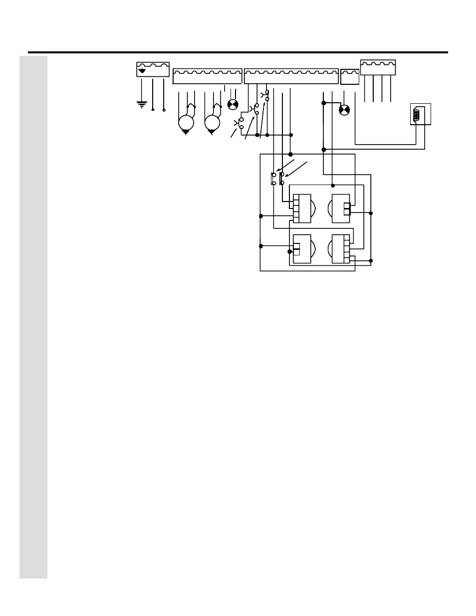
NOTE: In order to comply with UL 325, two sets
of FAAC photobeams must be installed. One set
should be 6 in. outside the closed gate(s) and act
as a closing reversing device. Another set should
be 6 in. beyond the swing of the gate(s) and act
as an opening reversing device. T he installer is
responsible for determining the appropriate
mounting height.
22 23 24 25
1
2
3
4
5
6
7
8
N
L
9
10 11 12 13 14 15 16 17 18 19
115 VAC +/- 10%
or
230 VAC +6/ -10%
50-60 Hz
20 21
-
STOP
OPEN
OPEN
(1 of 2)
24V
+
FSW
OP
CL
-
FSW
-
-
+
W.LIGHT
24 vdc
3 W
LOCK
ELECTRIC LOCK
1
2
1
2
3
4
5
1
2
3
4
5
1
2
FSWOP
FSWCL
Other safeties
LAMP
BL
UE
MOTOR 1
C1
M1
OP
COM
CL
BL
UE
MOTOR 2
C2
M2
OP
COM
CL
FOR WHEN THE FAAC
GATECODERS ARE USED
Page 24
June, 2004
750 Operator And
455 D Control Panel Installation Manual
Figure 2-CP.
The terminal strip wiring of the
455 D with photobeams
You cannot check the motor’s direction of rotation
without these circuits (jumpers) or the accessories.
When properly prepared for testing, the LEDS FSWOP,
STOP, and FSWCL should be illuminated (see Figure 4-
CP).
WARNING! Running the operator—even for
testing purposes—without a connected reversing
device is potentially dangerous. Do not place
yourself within the path of the moving gate
during your test.
Disengage the operator(s) with the Manual Release
key (see operator installation manual), and open the
gate by hand about halfway.
Next, engage the operator(s) with the Manual Release
key so that you can check the rotation of the
motor(s).
To activate the operator(s) momentarily short across
terminals 9 and 14.
Turn on the main power and send an activating signal
to the operator. The gate leaf (or leaves) should open.
If a gate leaf closes, then you need to turn off the
main power and reverse the connection of the red
and black wires on terminal block J4 for the operator
controlling that leaf. Then you need to recheck the
rotation direction again.
After having completed your test of the motor’s
direction of rotation, replace any test circuits you
installed (between terminals 11 and 16, between 12
and 19, and between 13 and 19) with the proper
reversing and stop devices. The instructions for
installing such accessories follow.
C
ONNECT
O
THER
D
EVICES
WARNING! Turn the main power off before you
make any electrical connections.
P
OWER
S
UPPLY
FOR
A
CCESSORIES
: You can access a 24
VDC output for supplying power to accessories
through terminals 17 or 18, (+) and 14 or 15 or 16,
(-) on terminal block J1. In most cases, this source
can be used to power 24 VDC accessories.
N
OTE
: The 455 D control panel allows a
maximum accessory load of 800 mA.
R
EVERSING
D
EVICES
: Reversing devices include
photocells, inductive loops, and so forth. All of the
reversing devices should have contacts of the
normally closed (N.C.) type. Where you connect a
device depends on whether you want the device to
operate during opening or during closing.
N
OTE
: UL does not recognize the FAAC system
with loop detectors or safety edges. FAAC
photobeams must be used to comply with UL
325.
To wire photobeams, refer to Figure 2-CP (see FSWOP
for opening photobeams, and FSWCL for closing
photobeams). Photobeams must be connected as
shown. See Figure 5-CP for the wiring of inductive
loops. If using more than one reversing device, they
must be wired in series.
T
HE
455 D
C
ONT
R
OL
P
ANE
L
I
NS
TA
LLA
T
IO
N
I
NS
TRU
C
T
IONS