455 d c – Controlled Products Systems Group 107725 User Manual
Page 12
Page 12
June, 2004
750 Operator And
455 D Control Panel Installation Manual
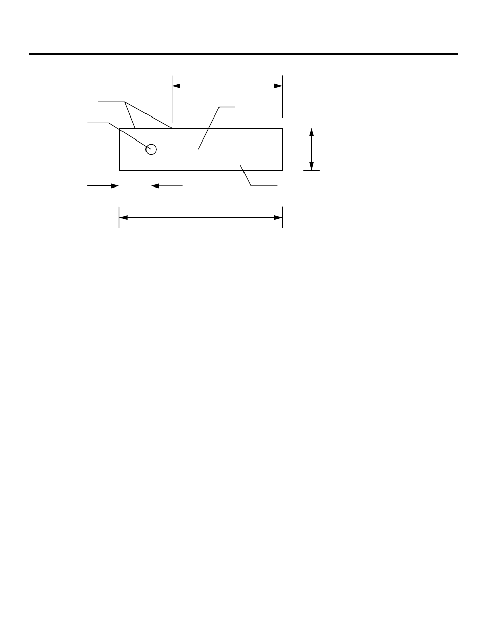
Axis of rotation
for gate leaf
Centerline of
gate leaf
Vertical section can be
located on either side
of axis of rotation
Minimum of
3/4 in. (1.9 cm)
Recommended minimum of 10 in. (25 cm)
Thickness
of the
gate leaf
Bottom of
U-shaped
section
Absolute minimum of 5 in. (12.7 cm)
between vertical section and end of
U-shaped section
Figure 10. Top view of the U-shaped
section of the gate leaf shoe.
I
NSTALL
THE
G
ATE
L
EAF
If you are not using the telescoping shear-pin assembly,
install the gate leaf by placing its 90-deg corner into the
gate leaf shoe and then installing the top gate hinge.
Installing the top gate hinge may require the gate leaf
to be at a particular height. To raise (or lower) the gate
leaf to the proper height, equally adjust the four leveling
bolts on the base of the drive unit. The bolts raise (or
lower) the splined shaft and thus the gate leaf shoe and
gate leaf.
To test the installation of the gate leaf, first make sure
that the hydraulic system has been disengaged (the
Manual Release lever should point down).
Next, very slowly open and close the gate leaf a few
times to see if it moves smoothly and evenly through its
entire path. As necessary, adjust the leveling bolts on
the base of the drive unit to correct any problems with
the gate’s travel.
I
NSTALLING
THE
455 D C
ONTROL
P
ANEL
Installing the control panel consists of the following
general steps:
•
Connecting the main power to the control
panel
•
Connecting the activating device
•
Connecting the operator to the control panel
•
Checking the direction of the motor's rotation
•
Connecting other devices to the control panel
•
Set operating modes
The installer is responsible for grounding the gate and
operator systems, for providing the main power breaker
switch, and for making sure that the entire gate system
meets all applicable electrical codes.
For the complete 455 D Control Panel Installation
Instructions, see pages 22 - 33 of this manual.
B
LEEDING
THE
H
YDRAULIC
S
YSTEM
For the 750 Operator to work smoothly, it is critical that
you bleed the hydraulic system of any air. Before you
bleed the system, be sure that you have removed the
vent screw on the top, left side of the power unit.
One bleeding operation consists of the following:
•
Running the gate leaf through three open-close
cycles
•
Allowing the gate leaf system to sit idle for
5 minutes
•
Releasing the air from each end of the drive unit
through the bleed screw holes (see Figure 1)
You need to bleed the hydraulic system before setting
the gate up for normal operation.
To run the gate leaf through an open-close cycle, make
sure the gate is set up for hydraulic operation (the
Manual Release lever is turned up) in the A mode.
Activate the gate once to open, pause, and then
automatically close. The gate needs to open and close
three times.
Then you need to allow the gate to sit idle for a full five
minutes. During this time, you can disengage the
hydraulic system (turn the Manual Release lever down)
and make sure that the top cover is removed from the
drive unit to allow you access to the bleed screws on
either end of the unit.