Controlled Products Systems Group 107725 User Manual
Page 10
C
ONNECT
THE
H
YDRAULIC
L
INES
Caution: It is important that the hydraulic lines
be kept clean of any debris.
The drive unit and power unit are connected by two
hydraulic lines, each with an outside diameter of 5/16 in.
(0.8 cm), an inside diameter of 5/32 in. (0.4 cm), and a
2,500 psi (170 bar) rating.
Caution: After removing the nylon piping, do not
rotate the splined shaft while you are connecting the
hydraulic lines to avoid squirting hydraulic fluid.
Remove the nylon piping connecting the two hydraulic
pipe fittings on the drive unit. Clean up any spilled
hydraulic fluid.
Be sure the hydraulic lines are free of any debris by
flushing them with a jet of compressed air. Then attach
one line to each fitting on the drive unit.
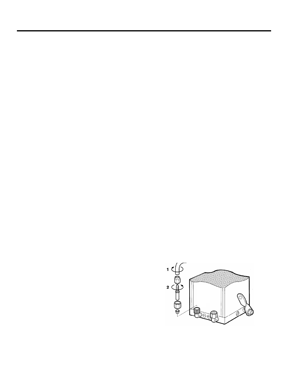
Next you attach the other end of the hydraulic lines to the
pipe fittings on the power unit (see Figure 7; additional
information can be found in the technical drawing on
page 21. Attaching the correct line to the correct fitting is
important. Make sure that the hose on the end of the
drive unit that is on the closing side of the gate/fence line
attaches to the hydraulic pipe fitting in the power unit
that is nearest the green bypass valve screw. This
connection insures that the green valve controls opening
pressure.
S
YNCHRONIZE
THE
H
YDRAULIC
S
YSTEM
Next you need to disengage the hydraulic system in order
to synchronize it.
Inside the power unit is the Manual Release lever that
disengages the hydraulic system (see Figure 1). Make sure
the Manual Release lever is turned toward you and down
to disengage the hydraulic system.
Now you can synchronize (set) the hydraulic system to the
closed position by turning the splined shaft in the closing
direction. Turn the shaft as far as it will go. To prevent
the piston in the drive unit from bottoming in its cylinder,
next turn the splined shaft about 5 deg in the opening
direction.
The position of the shaft now corresponds to the fully
closed position of the gate leaf. The hydraulic system is
now synchronized (set).
Caution: The splined shaft must not be moved from
its closed position until the gate leaf shoe that holds
the gate leaf has been attached.
Figure 7. Connect the hydraulic line to the power unit.
See the technical drawing on page 21 for more infor-
mation.
Page 10
June, 2004
750 Operator And
455 D Control Panel Installation Manual
I
NSTALL
THE
G
ATE
L
EAF
S
HOE
If the vertical distance between the finished grade
under the gate and the bottom of the gate leaf is
more than 1 1/4 in. (see Figure 4), you need to do one
of the following:
•
Install a length of appropriately sized pipe
between the sleeve that fits around the splined
shaft of the operator and the gate leaf shoe.
•
Construct a shear-pin assembly to accommodate
the extra vertical distance. The assembly is
welded to the bottom of the gate leaf shoe on one
end and to the sleeve for the splined shaft of the
pinion on the other end (see Figures 8 and 9).
Such an assembly requires a bottom hinge and
also protects the pinion and splined shaft in the
event something hits the gate with great force.
Installing the gate leaf shoe involves making the gate
leaf shoe, positioning it, and welding it to the splined
shaft sleeve. If you are retrofitting the 750 Operator
to an existing gate, these tasks require you to remove
the gate leaf from its hinges. If you are using a shear-
pin assembly, refer to Figures 9 and 10 to determine
what you should weld together.
The gate leaf shoe is designed to carry the weight of
the gate leaf and transfer the weight to the splined
shaft. The shoe surrounds the 90-deg gate-post
corner of the gate leaf to carry the gate and to act as
a lower hinge. The shoe is made of a U-shaped
section and a vertical section (see Figure 9). Later you
will weld the bottom of the U-shaped section to the
sleeve for the splined shaft (or to the shear-pin
assembly, which is welded to the sleeve).
Since the gate leaf shoe holds the gate leaf, both
sections must be made of steel at least 1/4 in. (0.6
cm) thick. The U-shaped section of the shoe must be