455 d c, Ontrol, Ane l – Controlled Products Systems Group 107725 User Manual
Page 25: Ns t a lla t ion, Ns tr u c tions
F S W O P
F S W C L
O P _ A
O P _ B
S T O P
F C A 1
F C A 2
F C C 1
F C C 2
Page 25
June, 2004
750 Operator And
455 D Control Panel Installation Manual
A
CTIVATING
D
EVICES
AND
R
ADIO
R
ECEIVER
: The activating
devices and radio receiver for your gate must have
normally open (N.O.) contacts. Connect such devices to
terminals 9 and 14.
N
OTE
: The FAAC radio receiver plugs into the 5
prongs labeled J2 (Quick connect port).
Figure 5-CP shows how to connect a three or four wire
receiver.
D
ECODER
C
ARD
: If you are installing the Digicard
magnetic card reader, or the Digikey keyboard, use the
quick-fit connector J2 for the DS decoder card (see
Figure 1-CP).
N
OTE
: If your using both a receiver and decoder,
hard wire the decoder and plug in the receiver.
O
PEN
/H
OLD
O
PEN
D
EVICE
: To open and hold open the
gate, simply maintain a contact across terminals 9 and
14. (“A” Mode only)
S
TOP
B
UTTON
: The stop button you install must have
normally closed (N.C.) contacts. Multiple stop buttons
must be wired in series. Connect your stop device
between terminals 11 and 16.
N
OTE
: The 455 will not operate the motors without
a closed circuit between 11 & 16.
The LED Indicators: The nine light emitting diodes
(LEDs) on the control panel can be used to check for the
proper function of the devices attached to the panel.
The LED lights are on whenever the contacts are closed
across each of the respective terminals.
OP_A and OP_B (Partial Opening) should illuminate only
when an activating signal is sent for 2 and 1 gate
leaves, respectively. STOP should be illuminated except
when the stop button is pressed. FSWOP and FSWCL
should be illuminated except when the reversing
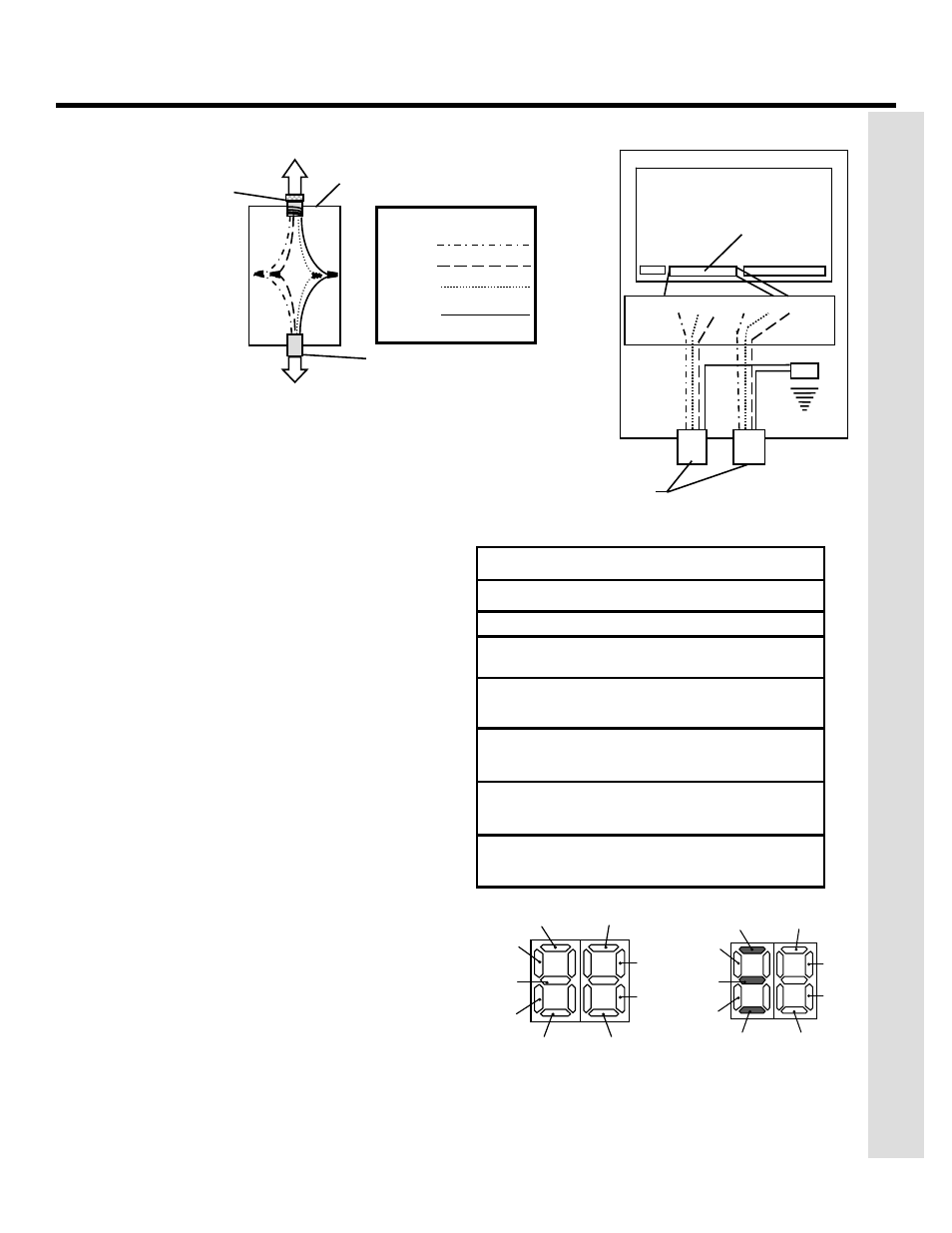
Figure 3-CP.
Wiring detail (a) inside
the junction box and (b)
from the junction box or
operator to the high-
voltage terminal strip on
the 455 D control panel
LED
On
Off
OP_A
Command Given
No Command
OP_B
Command Given
No Command
Stop
No Command
Command Given
FSW
Open
Opening reversing
devices clear
Reversing device
triggered
FSW
Close
Closing reversing
devices clear
Reversing device
triggered
FCA1
FCC1
Flashes when gate coder is in use.
Operator 1
FCA 2
FCC 2
Flashes when gate coder is in use.
Operator 2
U.L. Listed Control Panel Enclosure
Cord grip or
conduit from
U.L. Listed gate
operator(s)
(b)
Op.1
Op.2
COM OP CL COM OP CL
J3
J4
High-voltage
terminal strip
455 MPS Control Panel
Ground
J1
To the U. L. Listed gate operator
To the U.L. Listed
control panel
U.L. Listed
cord grip
Junction box
Legend
White
Red
Black
Yellow/
Green
(a)
Conduit to U.L. Listed
control panel enclosure
according to N.E.C.
FSWOP
FSWCL
OP_A
OP_B
STOP
FCA1
FCA2
FCC1
FCC2
This display shows the normal
status of the control panel.
This display shows the
meaning of each LED.
Figure 4-CP. The 455 D display.
T
HE
455 D C
ONTROL
P
ANE
L
I
NS
T
A
LLA
T
ION
I
NS
TR
U
C
TIONS