750 o – Controlled Products Systems Group 107725 User Manual
Page 7
Page 7
June, 2004
750 Operator And
455 D Control Panel Installation Manual
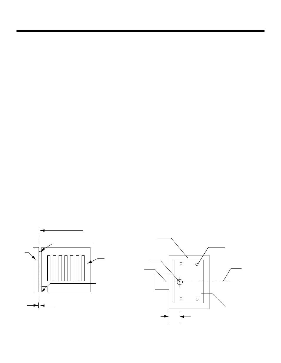
Figure 3. Recommended dimensions for the concrete footing and
foundation plate, top view
Figure 2. Constraints on the geometry of
the gate leaf.
2. The distance between the gate post and the
center of the gate hinge must be at least 2 3/8
in. (6 cm).
3. Make sure the gate leaf has positive stops in
both the opening and closing directions (see
Figure 3).
Note: If you are installing the 750 Operator with an
extension arm, some of the constraints about the
gate leaf may not apply to you. See the section
"Installing an Extension Arm" for more information
on page 14 & 15.
I
NSTALLING
THE
750 O
PERATOR
Installing the 750 Operator consists of the
following steps:
• Setting the concrete forms
• Installing the power unit
• Installing the drive unit
• Connecting the hydraulic lines
• Synchronizing the hydraulic system
• Installing the gate leaf shoe
• Installing the gate leaf
• Installing the control panel
• Adjusting the hydraulic pressures for the
operator
• Checking the motor rotation
• Bleeding the hydraulic system
• Adjusting the bypass valves
S
ET
THE
C
ONCRETE
F
ORMS
You need to lay out the concrete forms according to the
dimensions shown in Figures 3 and 4. (Your soil
conditions will also determine the size of the cement
footing.)
Note: If the vertical distance between the finished
grade and the bottom of the gate leaf exceeds 1 1/4
in. (3.3 cm) as shown in Figure 4, you can install a
shear-pin assembly as shown in Figure 8 and as
discussed in “Installing the Gate Leaf Shoe.”
Accurately positioning the foundation plate beneath the
gate hinge is critical especially if it supports the drive
unit, which supports the gate leaf.
Note: The foundation plate may be supplied by the
installer. If so, it must meet the specifications
shown in Figure 3.
Note: Insure that the cavity where the drive unit is
located is well drained by means of pipes, gravel
drainage, or both, whatever is appropriate for your
soil conditions.
After the concrete is poured in the form and before it
has a chance to set, insert the foundation plate into the
cement and position it so that it is flush with the top of
the concrete and is level.
Allow the concrete to set a minimum of two full days
before you install the drive unit on top of it.
Gate leaf
90-deg corner
on gate leaf
One hinge holding
the gate leaf
Axis of rotation for gate
leaf falls through the
center of the hinge
Gate
post
Minimum of 2 1/4 in. (5.7 cm)
between axis of rotation and
edge of gate post
Centerline of
gate leaf
Cement
footing
Foundation plate,
10 x 18 in.
(25.4 x 45.7 cm)
Axis of rotation
of gate leaf
Gate
post
Minimum of
2
1
/
4
in. (5.7 cm),
maximum of
5
1
/
4
in. (13.3 cm)
One of 4 bolts that
anchor plate into
cement footing