8” from ground – Kolpin 86400 – UTV 72” Snow Plow User Manual
Page 6
6
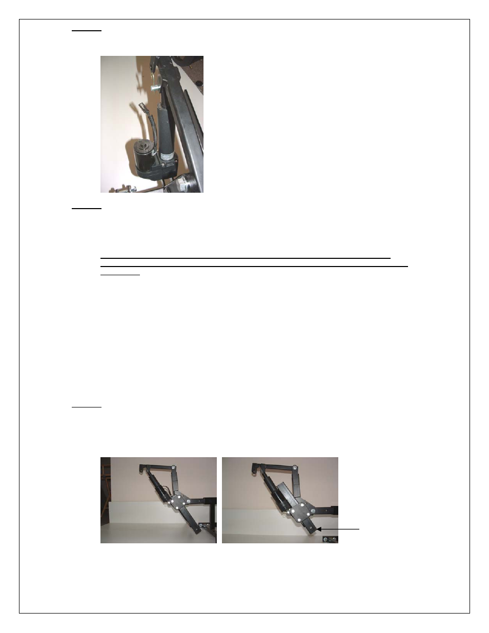
Step #10
1. Locate Electric Actuator #56 and (2) each of hardware #10 and #11.
2. See picture below for actuator positioning and secure with pivot pin #10 and “R” Clips #11 as
shown in picture below.
Step #11
1. Locate Wiring Harness #55.
2. Locate Battery on the vehicle that the UTV Snow Plow is to be used on.
3. Locate an area within reach of the driver that is convenient for operation of the switch.
4. A ½” hole is going to be needed to be drilled in the dash board or other user determined location to
mount the switch for this step.
*** Caution: Locate and drill hole only after you have inspected the location and have
determined that you will not drill into any hidden components that could cause damage to
the vehicle.
5. Route Wiring harness actuator end to the front f the vehicle. Be sure not to route the wiring around
or through any areas that could cause damage to wiring due to wear or heat. Avoid all moving parts
and secure with nylon ties if needed (not included).
*** You may choose to secure wiring routed through frame using the provided Black Corrugated
Wire Loom provided in this kit. This will provide additional abrasion protection.
6. Secure Switch from back side of drilled hole with fastening nut and washer provided.
7. Secure Battery terminal ends to battery in the following sequence. Secure + (Positive RED side)
this is the wire harness side that has the circuit breaker secured to it to the + (Positive) side of the
battery.
8. Secure - (Negative BLACK side) this is the other wire side opposite of the circuit breaker secured to
it to the - (Negative) side of the battery.
Step #12
1. Insert main lift assembly into receiver hitch located on the plow vehicle.
2. Secure with (1) 5/8” x 3” Bent Hitch Pins and ”R” Clip.
3. As you will see in the pictures below, the Blade Height Frame is adjustable up and down by loosing
the (4) ½” bolts and locating the frame at a desired height. It is recommended that you adjust this to
be approximately no less than 8” from the ground for proper blade angle and lifting height.
4. That dimension is to the lower hole located at the bottom of the Blade Height Frame.
8” from Ground